Thursday, 18 March 2010

The Adoption of Testable Architecture to Model Service Discovery Mechanism within a Distributed system

Overview
This paper reports on the study that has been carried out on the process of designing the capability of service discovery within the mechanics of a distributed architecture to supports the paradigm of service oriented. Using classical software modelling tools, the ability to model discovery capabilities is constrained due to the static nature of the tools. We are required to adopt the approach of inductive modelling discipline, i.e. the formulation of dynamic models in order to test the model against a yield that conforms to the dynamic nature of distributed behaviours during the act of communicating. Service discovery is typically a dynamic facet of distributed models and due to the fact that there are different discovery approaches, we need to know, upfront, which ones best conform to the character of the distributed model one is planning to build. Testable architecture (TA), with its advances to accomodate the formalism of Coloured Petri Nets, to complement pi-calculus provide the neccessary framework and mathematical rigour to model the dynamism of service discovery before any lines of codes have to be created. This helps to reduce the cost of development by reducing the rate of defect injections, from design to build, since the phenomenon of emergent behaviours amongst communicating behaviours can be tested and be revealed at the early stage of the Software Development Life Cycle (SDLC). In our study we exploit TA to provide us with a simulation environment in order to model and test the dynamic behaviours of distributed systems for the problematic of service discovery.

Service Discovery
The word discovery, as the oxford dictionary illustrates, is the act or process of finding out or becoming aware of what was yet not found (Oxf03). In the context of the network engineering, service discovery is a method of determining and instantiating the resources required to manage and operate network entities and their associated software composition. The latter are often deployed across multiple nodes within a cluster and communicate with each other to mutually form a series of defined services. Existing models to service discovery have been developed primarily for fixed network backbone environments and typically rely on centralised components being accessible to potential service clients at any given time (Gutt99, Arn99 and Mic99). In highly dynamic nature of underlying network topology, these models lack the designated service infrastructures, hence rendering such discovery mechanisms unsuitable for ad hoc environments. The concept of service discovery is well established in distributed systems, since networked entities need to discover available remote resources (Mull85). Work on service discovery focus on using decentralised architectures to overcome the limitations of traditional discovery mechanisms, such as Service Location Protocol (SLP) (Gutt99), Jini (Arn99) and UPnP (Mic99), which rely on fixed infrastructure. Research in service discovery architectures for mobile environments can be classified into lower layer service discovery protocols (Haa99, li00 Xue01 and Koz03) and higher-layer service platforms (Herm00, Chak02 and Hel02). Service discovery protocols emphasise on efficiency and distributed infrastructure while service platforms focus on providing a middleware layer that enables applications to use a service oriented programming model. The reader should note that the works carried out on service discovery architectures, (Zhu02, Cho05 and Enge05), provide a survey and an evaluation analysis of different service discovery models.

In our study we place emphasis on the higher layer service platform, with the objective of designing and simulating the different service discovery strategies in the context of distributed messaging services. The aim is to model and build fast and robust service discovery strategies, which are the main drivers for efficient management and organisation of distributed system.

Structure & Data Model
The data model explains the relationships between the known entities, showing how services are provided by a given application (see Figure 1). It also shows how the participants or software components and the physical nodes relate to each other within a cluster by means of service discovery strategies.

Figure 1 ERD of Service Discovery Model
The Entity Relationship Diagram (ERD) in Figure 1, shows that the entity Service Discovery Strategy has many types, (entity Types) which defines the properties of a distinct strategy and the cluster of nodes they manage. The purpose of the Service Discovery Strategy is to locate a particular service, represented by the association search for entity Service. This association will define the route, shown by entity Route, which will be used by a node to process a particular service. The entity Route describes the connectivity model between nodes and associated services.

The Communication Model of Service Discovery
The communication model for the purpose of service discovery explains two essential concepts.
Communication Agreement Model
The communication agreement model describes the five distinct states of affairs during the deployment and run time of a cluster of services. It shows that there are defined sequences of operations at a distinct phase of the network life cycle. The five communication agreement models are as follows:
o Cluster Establishment (CE)
o Cluster Maintenance (CM)
o Service Agent Establishment (SAEST)
o Service Agent Enablement (SAEN)
o Service Agent Maintenance (SAM)
Communication Styles
The communication style defines the manner in which information is exchanged and how it determines the service discovery strategy. We considered the four most common strategies of service discovery:
o Exhaustive search
o Broadcast All acknowledge
o Broadcast 1 acknowledge
o Transactional publish subscribe
The hypothesis states that the implementation of a particular communication style depends on the type of communication agreement model in place which implies that using only one type of service discovery strategy e.g. broadcast, to manage all types of communication agreement models may be not efficient and eventually implausible to manage as the system evolves. The study has been designed to validate the hypothesis and applies a blended modelling approach to join simulation models with the qualitative modelling techniques.
Communication Agreement Model
The communication agreement model represents the distinct states of a cluster within a defined life cycle. It holds a collection of operations which are enforced by a cluster manager in order to start, run and maintain a system. We have identified 5 distinct collections of operations and each of them is carried out using one or more service discovery strategies. Subject to the type of operations in place and the state of a cluster, each of the service discovery strategies has different properties influencing the overall quality of a system.
Cluster Establishment
In order for a cluster to be established, the service manager initiates the start-up sequence within a physical node, and attempts to discover the availability of other nodes within the cluster (see Figure 2). It establishes a communication channel between each active node and these allow for the transfer of heartbeats between Service Managers as well as updates regarding service agent establishment and service agent maintenance messages across the cluster. If more than one service manager is active, a mechanism should determine a Master Service Manager for the Cluster and information from the master should be distributed to Slave Service Managers. Both master and slave service managers are Local Service Managers for their respective nodes. Should no other service managers be found during the start-up sequence, the started service manager begins service agent establishment.

Figure 2 Cluster Establishment

Cluster Maintenance
In order for a Cluster to be maintained, the master service manager should be capable of handling the introduction and removal of slave service managers (essentially the addition or removal of nodes from the cluster). Should the master service manager fail, one of the remaining (if any) slave service managers should adopt the role of a master service manager. This may result in service agent establishment, enablement and maintenance as necessary which are described below.
Service Agent Establishment
In order for a Cluster to be fully functional, the Local Service Manager should be capable of starting Service Agents upon the node as determined by the Master Service Manager (see Figure 3). The Local Service manager controls different types of service agents which are responsible for distinct tasks. For instance a particular Service agent may be responsible for managing the connection to external entities such as Billing Platforms, whereas others are responsible for Customer Data Managements.

Figure 3 Service Agent Establishment

Service Agent Enablement
Service agent enablement is the process wherein the local service managers, instantiate service agents on individual nodes and report the start-up status to the master service manager. The master service manager will then issue routing information to the local service managers, which is then propagated to the service agents on each node. The master service Manager upon validation that the minimum required agent base is available to run an application instance e.g. an underwriting workflow, should issue a signal to the local service managers to inform the service components to initiates business process. Figure 4, shows an example of service agent communication across a cluster and the communication channels between service agents. The communication between the service managers’ communication and service agents is not shown for diagram simplicity.

Figure 4 Service Agent Enablement

Service Agent Maintenance
Service agent maintenance is performed by a local service manager and is responsible for handling the start-up and shutdown of service agents as determined by the master service manager. The Local Service Manager is also responsible for reporting to the Master Service manager any failure of a Service Agent so that it can be instantiated elsewhere within the cluster.

Communication Styles

We define communication styles as the ways or manner information is conveyed across dispersed nodes within a cluster. The communication styles are the different strategies applied to locate and instantiate services within a cluster of services. As mentioned earlier, the discovery strategies are available with various properties and can be broken down into the following categories:
Exhaustive Search Strategy
Exhaustive search is a brute force method where a service polls for information against the known services until the desired response is received (see Figure 5).


Figure 5 Operational Model of the Exhaustive Search Strategy

With an exhaustive search any service will iteratively poll other services starting with the first, wait for a response and if the result is negative will continue to the second and await its response until such time as the desired response is obtained or no further services to be polled remain.

Broadcast Strategy
Broadcast discovery is a method where a polling service broadcasts a request to a number of services in order to receive a response. This is normally an information request or a request for something to be processed. There are two models which can be considered:

Broadcast (All Respond)
With the “Broadcast All Respond” model, all services that can possibly handle a request are transmitted and each polled service issues a request response (see Figure 6). This request response can be either a positive response indicating a service has been performed successfully or an information response passing data to the polling service. It can also be a negative response indicating that the service request cannot be performed or the information requested is not available or accessible by the polled service. The polling service should have a timeout mechanism if only unsuccessful responses or no response be forthcoming.


Figure 6 Operational Model of the Broadcast Strategy

Broadcast (Active Respond)
With the “Broadcast Active Respond” model (see Figure 7), all services that can possibly handle a service request are transmitted however only polled services that can issue a positive response indicating a service has been performed successfully or return data to the polling service, responds. All other services continue as if the service request was never received. The polling service should have a timeout mechanism if no response be forthcoming.


Figure 7 Operational Model of the Broadcast Active Respond Strategy

Transactional Publish Subscribe Strategy
The “Transactional Publish/Subscribe” method involves publishing a service request to a list (see Figure 8). The service request list is a FIFO list and any servicing entity may remove the first request from a list, however only one service may subscribe to process a single service request. Upon completion of a service request the servicing entity sends its response to the Posting service. It is possible to have multiple posting services publishing to the same service list. The posting service should have a timeout mechanism to recover if a response to a published request is not forthcoming.


Figure 8 Operational Model of the TP Subscribe Strategy

As part of the “Transactional Publish/Subscribe” method the question arises as to where the location of a service list resides and if the list should have local copies (caches) located across the cluster rather than in a central location. The relevance of whether a local cache is advantageous depends on the nature of the data stored within the service list. Data which has a short life span is less suitable for caching locally than data that has a longer life span. Also data that requires constant updating is less suitable to local caching than any data that has a fixed value. The reason for this is that constant updating of the primary list affects all cached lists and updating of the local caches requires significantly more resources than simply the maintenance of the primary list. As the number of caches increases so does the amount of required resources to maintain them.
All the above discussed strategies, share a common format in that services expose an availability notice to the service discovery element and running services communicate to each other using one or more of the strategies mentioned.

Simulation Model

In this section we demonstrate the use of TA to formulate the dynamic Petri Net models of service discovery mechanism so as to validate which discovery strategy best conforms to the SLAs and quality requirements of the system. As mentioned earlier, there are five communication agreement models that define the state of a cluster within a life cycle. The following sections show the characteristics of the communication agreement models to understand the frequency of their occurrences within the life cycle of a cluster and to test each service discovery strategy (communication style) against each of the communication agreement models.

Cluster Establishment
Cluster establishment happens once in the system life cycle, at initialising time. There are several service managers and each manager is required to know about their neighbouring services. The simulation performs a many to many relationships between the service managers wherein all service discovery strategies compete with each other to find the best strategy for service discovery at that level.

Cluster Maintenance
Cluster Maintenance occurs periodically during the system life cycle. At run time, the master service manager communicates with the slave service managers to check their existence through distinct “heart beats” which is configurable. This process maintains a quorum defining the instance of a cluster, where the communication is based on one-to-many relationships.

Service Agent Establishment
Service agent establishment happens once during the system life cycle, when a cluster is established and its boundary is defined. The next operation is to identify and initiate the service agents within the cluster. The service managers communicate with the service agents, which is based on one-to-many relationships.

Service Agent Enablement
Service agent enablement happens once during the system life cycle. It concludes the final phase of initialising the service agents, after all the services have been established. In our scenario, the service enablement process will cluster all the related service agents to formulate a particular instance of a messaging gateway application. This is a many to many communication style of service discovery.

Service Agent Maintenance
Service agent maintenance occurs periodically during the system life cycle. In this state, service agents are connected and communicate to complete a typical service. During this operation, some information might be required from service agents, thus triggering service discovery, which is a many to many communication style of service discovery.

We observe that service discovery mechanisms are implemented at different states of a cluster life cycle and also that it is used at two phases of execution; 1) at initialisation time – frequency of occurrence is once, 2) during run time – frequency of occurrence is periodical.
In order to simulate the different service discovery scenarios, the high level description of the proposed communication styles are translated into a dynamic Petri Nets model.

The Broadcast Strategy
Figure 9, shows a number of configurable Places representing individual agents, where each of them has two states, ready and performing, depicted by the place Agent. When the simulation starts, the transition SendMessage is fired to broadcast discovery requests to all the clustered agents. The post condition of such flow is defined by the place sent which is of type TimedMSG. A message therefore, consists of a source and a destination. When a message is sent, the destination agents receive those messages which enable the transition ReceiveDTMessage to occur, firing the place received. On receipt, the agents process the message, shown by the transition ProcessMessage and acknowledges to the source which is done by firing the transition SendAcknowledgement. The place ack explains that the source agent has received an acknowledgement, i.e. the transition ReceivedAcknowledgement is fired. This ends the first round of broadcast strategy and another process with a different source is initiated. Figure 9 describes the discovery traffic that occurs during a broadcast where the Petri Nets distinguish between the application traffic and the network traffic. Application traffic is any type of traffic that is not related to service discovery but can request an initiation of service discovery. An analogy is a service agent dedicated to storage and its objective is to read from and write to databases. So the reading and writing of data exchange occurs over the application traffic.

Figure 9 CPN Model of the Broadcast Strategy

In Figure 9, there is a producer of events that causes application traffic by assigning a message for agent. When a message arrives, an agent fires the transition ReceivedNTMessage. Consequently the place arrived shows a message exist and an agent needs to process the message. The transition ProcessMessage is triggered and the place processed contains a resource which is a message. The final phase of the system is the transition Execute that occurs when the message leaves the system. Therefore the model allows agents to handle both application traffic and discovery traffic. The impact of network traffic over application traffic provides a key indicator of throughput performance which can be observed through simulation.

The Transactional Publish Subscribe Strategy
Figure 10 shows some similarities in the design of the broadcast and the Transactional Publish Subscribe (TPS). Transitions such as ReceiveDT/NTMessage, ProcessMessage and Execute perform the same tasks as described in the broadcast model. However, there exist an agent pools where agents are able to subscribe to a service for publishing information on a board. This is depicted by the transition SubscribeAgent, which after successfully subscribing to the board, represented by the place subscribed, the agents enters a FIFO queue, EnterAgentQueue and goes to the ready state, shown by the place ready. When the agents are in the ready state, three things may happen; 1) the agent may be a source and publish information on the board which will consequently fire the transition SendMessage; 2) The agent may be a destination and receives discovery traffic, shown by the transition ReceiveDTMessage, or 3) the agent may also be a handler which handles application traffic when a message event occurs.


Figure 10 CPN Model of the TPS Strategy

The Exhaustive Search Strategy
The Exhaustive search model (see Figure 11) is again very similar to the broadcast model. The difference is that in exhaustive search, the message from the transition SendMessage is not publicised. Here only, one message leaves the transition SendMessage and one destination agent receives it, shown by transition ReceiveDTMessage. The source agent will not send another message until it receives an acknowledgement from the destination agent. The place wake & sleep allows an agent to send a message but it needs to wait until it receives an acknowledgement from the destination to be able to ask another agent.


Figure 11 CPN Model of the Exhaustive Search Strategy

Application of Service Discovery Strategies to a typical Messaging Scenario
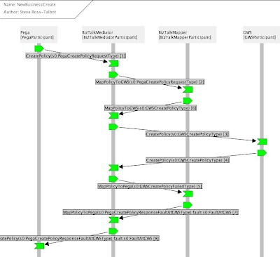
This section introduces a scenario, which attempts to position the concept of simulation and dynamic modelling into a real life situation of distributed messaging services. The process is called a Delivery Request which is a work flow model, designed to represent that a SMSC requires an acknowledgement that a message has been delivered to an IP based application. The objective of the simulation scenario is to find out which service discovery strategy (communication style) best conforms to the specifications of this particular work flow.

When the simulation starts, a transition ApplicationSendMSG sends message to the system, hence the place arrived indicates that a message has reached the system (see Figure 12). Upon arrival, the message is processed i.e. an agent is assigned to the message, resulting to the transition ProcessMessage to be fired. Each message has a ticketNo which is checked by the agent to know which SMSC the message is ought to be sent. If the agent does not know about the message, it finds it by triggering a service discovery mechanism. As mentioned there are three types of strategy, Broadcast (all respond / active respond); Transactional Publish Subscribe; Exhaustive Search. When an agent who knows about the existence of the message is found, it sends an acknowledgement to the sender, shown by the transition sendAcknowledgement. The sender receives the acknowledgement and fires the transition ReceiveAcknowledgement. Next the sender sends the message to the destination agent which is depicted by the transition SendMessageToAgent. The agent then sends the message to the committed SMSC, shown by the transition DeliverToSMSC. The Petri Net model was simulated wherein each service discovery strategy proposed was submitted to the test for a delivery request.


Figure 12 CPN Model of Delivery Request Model in Messaging

Observations
A cluster is complete after the service agent enablement state has been reached, thus all the service agents, that are required to complete a distinct messaging gateway application, are enabled. The service managers are responsible for one or more service agents. In order to establish a messaging gateway, the service managers need to find out about themselves and ask each other the type of service hosted.
We looked at the generic model of broadcasting, exhaustive search and transactional publish subscribe. Three simulations of 30,000 steps with one millisecond interval each, were executed. We change the agent population from 4 to 20 units for each simulation to address the quality attribute of Scalability. The first scenario considered was the process of establishing a cluster, referred to as the cluster establishment. After the simulation, we tested for the normality of the observed results, then conducted a 2 sample T Test (Park07) on the service discovery message processed per unit time. We then compared which strategy has a greater mean for message processed per second, i.e. the speed for processing service discovery message relating to the quality attribute of Performance.


Figure 13 Individual Value Plot of Broadcast vs. TPS Strategies

We plot the service discovery packet processed per millisecond of the broadcast strategy against the Transactional Publish Subscribe (TPS). We observed that the mean message processed per second of Broadcast is bigger than the one of TPS. The distribution shows that the Broadcast strategy allowed more messages per second to be processed by destination agents rather than TPS. Hence the likelihood of Broadcast strategy finding a bigger population of agents within a period of time in a system is greater than TPS. However, the standard deviation of Broadcast against its mean is bigger than that of the TPS where the individual plots are more crowded around the mean (see Figure 13). Yet the distribution of TPS is steadier which shows that the overall network traffic is more stable and reliable. This is understandable since within the TPS model, there exist a FIFO queuing model allowing only one agent to process only one message for each simulation turn and if there is a burst of incoming message, the message waits in the queue’s buffer instead of flooding the system. TPS provides reliable network mode, yet the drawback for such strategy is that message may pile up at the queue, and messages have to wait longer than, perhaps, the defined Service Level Agreement (SLA). The flexibility of such system lies on how elastic the FIFO queue is, i.e. dynamic adjustment of its buffer. When compared to the Transactional Publish Subscribe strategy, Exhaustive Search really shows that very few messages are processed per second, thus exhibiting poor performance. As the number of agents scaled up, the performance dropped drastically (see Figure 14).

Figure 14 Individual Value Plot of TPS vs. Exhaustive Strategies

So both performance and scalability were poor for the Exhaustive Search strategy. We can understand that because in exhaustive search, when the source is looking for a destination agent, he waits idly for an acknowledgement and then search for the following agents, and so on, thus within a given time period, less discovery message is processed. However, with the exhaustive search strategy, the process to looking for a service and waiting for an answer make the strategy more robust, which addresses the quality attribute of Robustness. Should the reply from the destination agent be critical and necessary, we demonstrate that the exhaustive search strategy provides more robust solutions.
In Figure 15, the Box plot of the broadcast strategy against the transactional publish subscribe strategy, is another representation of the number of message processed per second. The area of the Box Plot for Broadcast is larger than TPS and it shows the weight of the distribution for message processed per unit time against TPS. So far, we found that the Broadcast is faster in processing service discovery message per a given unit time than TPS but TPS is faster than Exhaustive Search. What is required to understand is how the three service discovery strategies influence the application traffic of the network. When sampling data for the T Test of application traffic, we observed that there were not sufficient data points for the broadcast strategy. This is due to the fact that compared to the other two service discovery strategies, the broadcast strategy processes far too little of the application traffic. This is logical and observable when we increased the number of agents in the CPN model to 20 agents; a broadcast strategy floods the system with service discovery messages leaving very few agents idle to process application traffic. This is the case when there is no network separation between application and service discovery traffic.


Figure 15 Box plot of Broadcast vs. TPS Strategies

Figure 16 shows a graphical visualisation of application traffic processing between the broadcast TPS strategies.


Figure 16 Throughput Performance of TPS vs. Broadcast Strategies

The result of the analysis compares the throughput performance of application traffic of two systems, one using a broadcast strategy for service discovery, and the other utilises transactional publish subscribe (TPS) method with each system hosting 20 software agents. It can be observed, that the worst case of deprivation for application traffic is when the broadcast strategy is implemented. Using the transactional publish subscribe strategy application traffic performance was observed to be much higher. We applied a two sample T test (Park07) to compare the mean of the number of application traffic messages processed per second for the transactional publish subscribe and exhaustive search strategies (see Figure 17).


Figure 17 Individual Plot of Exhaustive Search vs. TPS Strategies

We observed that the exhaustive strategy processes more of the application traffic than the TPS strategy. This is true because, within the Exhaustive Search strategy, one agent sends a discovery message and waits for an acknowledgement. While waiting, it is idle to carry out its application traffic, hence increasing the flow of application traffic in the system. However, if we look at transactional publish subscribe we see that the distribution of application traffic in Figure 17 is similar to the distribution of discovery traffic in Figure 13. This demonstrates that the transactional publish subscribe method more or less uniformly shares the load of application traffic and service discovery traffic that is essential to support high scalability. Figure 18 shows the comparisons of all three Service Discovery strategies applied for the single problem of Delivery Request (see Figure 12).


Figure 18 Broadcast, Exhaustive Search and TPS strategies in a Delivery Request Scenario

The metric used to draw the graph, in Figure 18, is the cumulated probability that a packet is delivered within 10 millisecond of its arrival. This graph compares the mean evolution of the probability for all three service discovery strategies and shows their performance. The ideal system would guarantee a mean of 1. As we can observe, the broadcast strategy is closer to 1 than the other two service discovery strategies. This is possible because the Petri Net in Figure 12 models the agents as a multi-threaded system and can run service discovery traffic and application traffic concurrently. That model makes the assumption that service discovery and application traffic run on separate networks which implies that the broadcast service discovery strategy has a higher probability of delivering a packet within a small time of its arrival on a multi-threaded model dichotomising the application traffic with the Service Discovery Traffic. However, we did that at a cost of introducing a new problem of economics, since threads consumes CPU processing time (resources).
Figure 19 shows the ratio of packet delivery over packet arrival within 10 ms and allows packet forwarding should the ratio be outside the 10 ms timeframe. This occurs when packets are not delivered in turn but wait in the system and are delivered in the next or next + n turn. The Box plot shows the performance and reliability of each strategy for delivery request. The standard deviation tells us that transactional publish subscribe is steadier for service discovery per message and the least steady is broadcast.

Figure 19 Box plot of Broadcast, Exhaustive Search and TPS strategies

So far what we have observed is that:
-Broadcast is faster than the other two strategies to discover new services
-Broadcast deprives the system from application traffic since the system is overwhelmed with discovery traffic.
- TPS more or less shares the application traffic and discovery traffic uniformly.
- TPS allows the system to run at a steady state due to the FIFO queue.
- ES allows more application traffic in the system and minimises discovery traffic.
On the grounds of our finding, we see that one service discovery strategy alone cannot conform to all requirements of the communication agreement models within a given distributed service model. At each phase of the communication life cycle a blended service discovery model is required as summarised in Table 1.

Table 1 Observational Matrix of the Service Discovery Model

Conclusion
We demonstrated how different service discovery strategies work across distributed nodes and how they influence the choice of communication styles. The results of the experiments demonstrated that one service discovery strategy alone cannot provide full compliance to the overall system requirements. This means that at various stages of system life cycle enacting different workflows or business processes, different types of service discovery strategies have to be implemented in order to manage the nodes. To know which strategy to use, we have to look at the characteristics and CTQs which are essential for that particular communication agreement model. The example that was considered shows that to establish a cluster of nodes, one of the CTQs is performance and one of the characteristics is the occurrence of that process. In this case the observational results illustrate that the Broadcast strategy matches the criteria and should be implemented as far as performance is concerned. Moreover, we also showed that the Broadcast strategy overwhelms the network traffic and is not recommended during high volume of application traffic. Since establishing a cluster happens only once during the system life cycle, prior to any application traffic, the strategy conforms to the characteristic of the communication agreement model. We have shown that this type of knowledge and study can only be obtained through dynamic modelling techniques and indeed such knowledge has been acquired from the simulation of Testable Architecture.

(Oxf03) Oxford University, “Oxford Dictionary of ENGLISH”, Oxford University Press, 2Rev Ed edition, August 2003
(Gutt99) Guttman E, Perkins C, Veizades J, Day M, “Service Location Protocol, Version 2”, IETF, 1999
(Arn99) Arnold K, Scheifler R, Waldo J, O'Sullivan B, Wollrath A, “Jini Specification”, Addison-Wesley Longman Publishing Co., 1999
(Mic99) Microsoft Corporation, “Universal Plug and Play: Background”, Microsoft Corporation, 1999(Mull85)
(Haa99) Haas Z J, Liang B, “Ad-Hoc Mobility Management with Randomized Database Groups”, in Proceedings of the IEEE International Conference on Communication, IEEE Computer Society, pp. 1756-1762, 1999
(li00) Li J, Jannotti J, Couto D S J D, Karger D R, Morris R, “A Scalable Location Service for Geographic Ad Hoc Routing”, in Proceedings of the 6th Annual International Conference on Mobile Computing and Networking, ACM Press, pp. 120-130, Boston, Massachusetts, USA, 2000
(Xue01) Xue Y, Li B, Nahrstedt K, “A Scalable Location Management Scheme in Mobile Ad-Hoc Networks”, in Proceedings of the 26th Annual IEEE Conference on Local Computer Networks: IEEE Computer Society, pp. 102-112, 2001
(Koz03) Kozat U C, Tassiulas L, “Network Layer Support for Service Discovery in Mobile Ad Hoc Networks”, in Proceedings of IEEE INFOCOM, vol. 23, IEEE Computer Society, pp. 1965-1975, 2003
(Herm00) Hermann R, Husemann D, Moser M, Nidd M, Rohner C, Schade A, “DEAPspace: Transient Ad-Hoc Networking of Pervasive Devices”, in Proc.of the 1st ACM International Symposium on Mobile Ad Hoc Networking & Computing, IEEE Press, pp. 133-134, Boston, Massachusetts, USA, 2000
(Chak02) Chakraborty D, Joshi A, Finin T, Yesha Y, “GSD: A Novel Group Based Service Discovery Protocol for MANETS”, in Proceedings of the 4th IEEE Conference on Mobile and Wireless Communications Networks,MWCN, IEEE Press, Stockholm, Sweden, 2002
(Hel02) Helal S, Desai N, Verma V, Lee C, “Konark: A Service Discovery and Delivery Protocol for Ad-hoc Networks”, in Proceedings of the 3rd IEEE Conference on Wireless Communication Networks WCNC, IEEE Press, New Orleans, USA:, 2002
(Zhu02) Zhu F, Mutka M, Ni L, “Classification of Service Discovery in Pervasive Computing Environments”, MSU-CSE-02-24, Michigan State University, 2002
(Cho05) Cho C, Lee D, “Survey of Service Discovery Architectures for Mobile Ad hoc Networks”, Mobile Computing, CEN 5531, Department of Computer and Information Science and Engineering, CICE, University of Florida, 2005
(Enge05) Engelstad P E, Zheng Y, “Evaluation of Service Discovery Architectures for Mobile Ad Hoc Networks, in Proceedings of the 2nd Annual Conference on Wireless On-demand Network Systems and Services, WONS, 2005
(Park07) Park H M, "Comparing Group Means: The T-test and One-way ANOVA Using Stata, SAS, and SPSS", Indiana University, 2007


Friday, 18 December 2009

Innovation Using TRIZ and Testable Architecture for the Formulation of a Broker Appointment System

Introduction
“Two pints of London Pride please” asked the underwriter.
“Would you like to keep a tab behind the bar?” asked the bartender
The underwriter turned to the broker and enquired
“How many risks shall we be negotiating today Bruce?”
“Around 7 of them” replied the broker
“Then yes, please open a tab for me” said the underwriter to the bartender

The London Insurance Market is a unique marketplace. For over 3 centuries, the relationship between broker and underwriter has transformed the London Insurance Market into one of the most dynamic and successful financial markets in the world. Whilst, it is traditionally a face-to-face business based within the area of the “City of London”, many of the participants have managed to achieve a global presence. Thus, this exclusive marketplace has continued to influence the global markets by being a major player by virtue of its efficiency and productivity.

Brokers play a pivotal role in placing large volumes of business in hands of Insurers on a daily basis. As a result the meeting between broker and underwriter becomes fundamental to the Insurance business. Many technologies have been proposed to enhance the meetings of broker and underwriter. Nevertheless, most the value propositions focussed on the aspect of collaborative tools that enable broker to virtually meet with underwriter over the Internet. Yet brokers and underwriters are always willing to meet each other, face-to-face, following a long and successful tradition, and utterly dislike any interfering technologies. Many of the online collaborative tools have failed to deliver value to both brokers and underwriters.

Unlike these traditional solutions, our business value proposition, which is the Mobile Broker Quest, is an innovative solution which does not attempt to act as a mediator in between the broker and the underwriter, but foster a catalyst to bring broker and underwriter together in a more efficient and prompt manner by focussing on the problem of broker appointment system.

Problem Statement

Traditionally, insurance companies provision a trading floor, with an appointment system, used by the brokers to book meetings with underwriters. One of the observed limitations of the existing appointment system is that the full capability of the service is constrained by the need for the broker to be physically present in the office. The waiting time is only known when the broker logs into system. Very often, the queue tends to be very too long, resulting to brokers leaving to meet other insurers or clients. The broker may or may not come back to the underwriter. This usually leads to an unsatisfactory customer experience and loss of potential business.

There is an apparent problem in the current broker appointment system at a major insurance group. When one profiles the statistics, it reports a drop of 60% in appointment booked since 2005. Brokers are not using the system anymore, since the solution does not offer the value they need. In identifying a process which is no longer supporting the goals of the underwriting process, this paper explains how an innovative solution, Mobile Broker Quest (MBQ), has been articulated and designed by merging two robust methods together, namely, The Theory of Inventive Problem Solving (TRIZ) [Kap96] and Testable Architecture (TA) [Tal04][Yang06] into a Blended Modelling Approach for innovation.

Blended Modelling Approach

The rationale behind the blended modelling approach is primarily due to the nature of a typical innovation life cycle. The variations which exist in an innovation process require more flexibility than the constraints of the classical software development life cycle. According to Garlan and Shaw, in their analysis of advances in software engineering [Gar93] [Shaw01], there is a lack of scientific rigour within software engineering, wherein structural design alone cannot exhaustively define a software problem. Since the yield of a given research cannot be known and guaranteed upfront, the mindset of formulating, inventing and treating requirements has to shift from a deterministic to a probabilistic method to manage the variations.

There are two acceptable attitudes of modelling, namely deductive modelling and inductive modelling [Oud02]. In the problem realm of deductive modelling, a model is an a priori representation of observed phenomena from reality wherein the process is to assume the model to be true upfront and the representation often becomes a structure which can be cloned or reproduced. These structures becomes moulds and knowledge from similar phenomenon observed in one’s problem domain can be “poured into these mould” which will lead to models of the problem definition. In the realm of inductive modelling, a model is an a posteriori representation of observed phenomena from reality and we understand that the reality and/or observation may change. Designers attempt to map the observations to a formal system so that these formalisms can be tested and simulated against the observations. Should the formal system be proven to be true, then a model exists, i.e. it has been induced, otherwise there is no existence of a model at this time.

In order to manage the variations and unknowns of an innovation process model, we are required to use both the inductive and deductive modelling techniques. This potentially adds scientific rigour to remove ambiguity in requirements, resolve design defects, increasing the power of modelling. However to join both discipline requires a robust framework. Our proposed blended modelling approach merges the 2 attitudes of modelling together using a formal and mathematical framework called Testable Architecture [Tal09].

The Mind Model of the AS – IS Process

We formulated a mind model by observing and learning from the customer problem domain. The point of focus was the trading floor at a global insurance group in London. Brokers need to be physically in the trading floor in order to enter the waiting line system by interacting with a touch screen interface, provisioning his/her credentials.


Figure 1 as -is Model of Broker Waiting Line System
The waiting time is known only after the appointment is booked in the queue and when the latter is too long; the broker may leave for other business. The may be a potential loss of business as Figure 1 depicts.

Quality Modelling

As we probed the underwriters and brokers on the issue of quality, there is a clear gap between the SLAs and the capability of the as-is process. The quality model required for the appointment system is, on the one hand, underwriters want more appointments in one day and better time management for their meetings, and on the other hand, brokers, being always on the move, require the flexibility to book appointment anytime and anywhere. We employed the House of Quality [Yoji90] to model the quality attributes and refine them to measurable and controllable attributes, as depicted in Figure 2.

The House of Quality


Figure 2 House of Quality of Broker Quest SLAs


We are left with two fundamental conflicting quality attributes, the ad-hocness of broker appointment requests, and the need for better time management from underwriter. In coupling the flaws of the AS-IS model with the conflicting quality attributes, we now apply a technique called TRIZ to guide the process of inventive problem solving.

The Implementation of the Theory of Inventive Problem Solving (TRIZ)

TRIZ is interdisciplinary and closely related to logic, psychology, history of technology and philosophy of science. The two basic principles in TRIZ 1) “Somebody, someplace, has already solved your problem or one similar to it. Creativity means finding that solution and adapting it to the current problem;” and 2) “Don't accept compromises. Eliminate them”. The main concept applied by Altshuller, the inventor of TRIZ, in developing the 40 principles is that contradictions (or trade-offs) are the constraints that inventions seek to resolve. Inventive solutions do not seek equilibrium along the trade-off, but “dissolve” the contradiction. Inventions are intended to solve problems which are fundamentally “the difference between what we have and what we want” (De Bono). The problems in turn are derived from contradictions. Any invention is therefore intended to “resolve” or “dissolve” these contradiction. From these premises Altshuller developed the 40 principles and the “Matrix of Contradictions”, see Figure 3.


Figure 3 The TRIZ Matrix of Contradictions

Within the problem domain of the Broker appointment system, we started by identifying the two core contradictions in the Broker and Underwriter relationship: 1) there is the need for the ad- hoc style of meeting from the brokers which is natural to their operation and they need the ease of operation to run their daily business while 2) there is the need for a better time management method from the underwriters to reduce the loss of time of an inefficient and uneconomical waiting line. In applying the TRIZ matrix, the following principles to solve these contradictions: Improving <25> Loss of Time without damaging <33> Ease of operation. As we traverse the matrix, Figure 3, we discover four principles which are defined as follows:
<4>Asymmetry means to change the shape of an object from symmetrical to asymmetrical and if an object is asymmetrical, then increase its degree of asymmetry.
<28> Mechanics substitution means to change from a static field to movable fields, i.e. to add another Sense to the solution.
<10> Preliminary action or Prior Action means to pre-arrange objects such that they come into action from the most convenient place and without losing time for their delivery.
<34> Discarding and recovering means to apply solution into the flexibility of transactions.
As observed, TRIZ does not provide the breakthrough idea, but spells out the principles to guide designers / innovators in catalysing the process of idea generation, i.e. the seed idea.

The Seed Idea

In translating the principles as prescribed by TRIZ, designed natively for the manufacturing domain, into the problematic of business process and software enablement, the following principles guides us to produce the seed idea. The latter comes from a mixture of understanding the pain points, potential enhancements of business processes creativity and the dissolution of contradictions. There is no process for creativity but there are indicators that can help to build an environment that fosters and directs creativity. The translation process harvested the following:
<4>Asymmetry means to change the symmetricity of the transactions into an asymmetric model, which indicate that the underwriter side of the appointment process has to be asymmetric to the broker side of the appointment process. This is an essential guiding principle as traditionally in software engineering, one tends to design solution that are structurally similar throughout the solution to improve manageability and reuse of solution components.
<28> Mechanics substitution means to change from static field to movable fields. The principle indicates the addition of another sense or channel to resolve the contradictions. The aspect of movable fields can be linked to the aspect of location and mobility, to the problem, that is the substitution of a static location for a dynamic one. In adding the aspect of mobility to the appointment system, leads us to look at the very common Mobile Technology.
<10> Preliminary action means to gather and prepare all the relevant documents required for underwriting the risk in advance and allowing the system to place them in the order required during the course of the meeting. These documents can also be pre provisioned with all known information such as date, broker details, underwriter details etc. which saves time during the meeting. This given principle reduces the duration of a meeting, hence creating more space in the waiting line to accommodate the ad-hocness of broker’s requests. Incorporating such feature dissolves the contradictions of time management i.e. reduce loss of time and ease of operation.
<34> Discarding and recovering means that the broker appointment system should be thin and flexible to use with fewer click and screens to complete a booking transaction. The principle also indicates that the underwriter should also provide the flexibility to delegate a meeting request amongst his/her peers. Hence, the seed idea can be formulated around the method and technology of 1) Mobile Technology; 2) Pre-provisioned, Positioned and Attach relevant documentation within appointment request, 3) Flexibility in changing appointment variables, e.g. Time and delegation of appointment amongst underwriters and 4)User Friendly Interface.

Requirement Invention

The seed idea is evaluated and rationalized in order to invent the user requirements of the solution. The process of translating the seed idea into requirement consist of fact-finding, identifying constraints as well as expanding information. This involves the analysis of the as-is model (see Figure 1) to understand the problem by delineating and refining constraints. Classically, in the problematic of software engineering, requirements are classified into two classes which are functional and non functional requirement [Boeh76]. However, it has been argued that user requirements have to be classified into their distinct styles which are more profound than the conventional two classes. The process of classification will provide the directives to which type of modelling tools, including inductive modelling tools, should be employed to the different styles of requirement. This is typically to address the approach of blended modelling which is supported by Testable Architecture. Typically, there are four types of the requirement styles which are 1) the data style, 2) the functional and logical style, 3) the communication and behavioural style and 4) the quality styles.


Table 1 Understanding the character of requirement

The TO – BE MODEL of the Mobile Broker Quest

We have formulated a series of high level requirements to how the Mobile Broker Quest will be operated leading to the design of the TO-BE process model (see Figure 4 ) designed to enhance the appointment system in conforming to the quality model or SLAs in Figure 2.

Figure 4 To- Be model of the Mobile Broker Quest

The to-be process model is in its static form, and we can experience some optimization feature in the reduction of the number of clicks required from the broker to provision the system when compared to the as-is model. Yet, in order to profoundly understand if the proposed model conforms to the SLAs and to maximise the probability of containing design defects, the static model has to be translated into a dynamic and formal model and this leads to the application of Testable Architecture.

The Application of Testable Architecture

A dynamic model is based on formal methods, subsequently enabling designer to type check and simulate the proposed model against the refined requirements and the quality model. This part of the modelling discipline is inductive and primarily it allows design and requirement defects to be found and fixed prior to coding. Testable Architecture (TA) is the core engine of the innovation process model and key to the success of the proposed idea, i.e. the Mobile Broker Quest. TA is a methodology that abstracts the complexity of formal methods, pi calculus [Miln80a] [Miln80b] [Miln93], Petri nets [Pet62] and Z Notation to provide a “run time simulation engine” and type check compiler to dynamic models. It fundamentally has the capability of blending structural modelling with inductive modelling, acting as a compiler to design and models. As we journey through the process of building a dynamic representation of the requirement that describe the phenomenon of two participants booking appointments, we are able to exercise the dynamic model to verify and validate against two key question: 1) Is the model representing the right thing?; and 2) Is the model representing the thing right?
In Figure 6, we illustrated the Coloured Petri Net Model of the to-be process highlighting the dynamics of the waiting line for Brokers. We exploited the simulation engine of CPN to assess the model against the quality attributes (see Figure 2) and constraints, to validate if the proposed model conforms to the business values and goals.Coloured Petri Net [Jeff91] is a modelling technique to model parallel behaviour and high-level programming languages to define data, functions, and computation on data. The process model is represented by token exchange between different parts of the Petri Net wherein places are connected to transitions via arcs. Tokens are inserted or removed from places, which carry, as a timestamp, the deterministic or randomly distributed temporal length of the transition they enable.


Figure 5 The Meta Model of the Mechanics of CPN

Formal and Dynamic Modelling

In Figure 6, we illustrate a Petri Net model of a waiting line component of the Broker appointment systems. We employ Petri Net to model the queue wherein simulation processes are performed to understand how the queues work under different condition, e.g. an increase in appointment request and continuously check against conformance. In order to emulate the dynamics of the waiting we use some of the historical data of the existing broker quest system and couple the statistics with some probabilistic model. Based on the empirical research of the queuing theory, we assigned the following distribution behind the CPN model for simulation 1) the arrival rate follows a Poisson distribution, 2) the buffering rate of the queue follows a normal distribution and the processing time of servers follows an Exponential distribution and the waiting line follows a FIFO structure.

Figure 6 CPN Model of the Waiting Line

Observations

Consider Figure 7, where given a burst of 1 appointment request per 10 minutes to 1 appointment request per 3 minutes, the graph shows the gap between the input rate against the output rate. It justifies that the close proximity between the input and output rate shows that the service rate of the Queue System is adequately lower than the input rate. The two graphs differentiate the latency added to the queue system.


Figure 7 Waiting Line Dynamics of Mobile Broker Quest

In Figure 8, the graph reports on the time taken for a large sample of appointment requests to leave the system. The objective is to estimate the number of brokers waiting for more than n minutes (where n is defined by the SLA) that exist given an input burst. The graph shows the period of time a number of brokers take to meet an underwriter, e.g. over hundred appointment requests, a broker take 12 minutes. Hence using such analysis, a threshold can be established to identify those brokers that have a probability of waiting for too long.

Figure 8 Waiting Time of Broker

In order to reduce the number of variables in the experiments, we employed the Taguchi Method of Design of Experiment (DoE), used to determine the relationship between the different factors (Xs) affecting a process and the output of that process (Y). In the defined quality model we are seeking the fundamental SLAs of the MBQ which is to increase the number of appointments in a day to increase revenue in new business. So the function exercised into DoE is as follows:


DoE establishes the most important Xs, of the function to reduce the number of simulations against the SLAs.The iterative process of simulating the dynamic model (see Figure 9) leads to the reinforcement and refinement of the requirements and containment of design defects [Boeh76]. The refined requirements are validated and transformed into formal specifications that are given to the designer of the solution architect.The iterative process of simulating the dynamic model (see Figure 9) leads to the reinforcement and refinement of the requirements and containment of design defects [Boeh76]. The refined requirements are validated and transformed into formal specifications that are given to the designer of the solution architect.

Figure 9 Iterative Refinement of Requirement


The Solution Architecture

The architecture lays the foundation for analytical optimization of function, cost, quality and performance by gaining understanding of: 1) how the system and the system elements function ideally; 2) understanding of the interfaces and their interactions and 3) the understanding of behaviours influenced by the interactions as formalized by Testable Architecture. The process of modelling the latter can only be formally understood by exercising Testable Architecture.

As the solution architecture is formulated, the continuity of the innovation life cycle follows the path of the classical Software Development Life Cycle for coding and testing which ideally fits into the constraints of the Spiral Model.

Conclusion

MBQ yields to an improved time management strategy, increasing the number of brokers an underwriter can meet. It fundamentally addresses the problem of customer intimacy and customer satisfaction as broker may plan their day in advance. The capability of MBQ enables the insurer to maximise the probability of winning of potential business by reducing the number of broker walkouts. In the journey towards the MBQ, we have demonstrated the application of TRIZ to successfully provide the principles required to enhance the process of seed idea generation. Those principles force us to think laterally which ensures that key attributes of a solution are not missed as they are very often during solution envisioning exercise. We also observed that Innovation endeavours carry several facets of the unknowns and variations that require inductive models to test their viability at the early stages of requirements. Hence, we proposed a blended modelling approach, founded on the discipline of Testable Architecture to apply simulation and validation to the proposed model of the broker appointment system.

Reference


[Boeh76] Boehm B W, “Software Engineering”, IEEE Trans. Computers, pp. 1,226 - 1,241, December 1976

[Gar93] Garlan D, Shaw M, “An Introduction to Software Architecture, in Advances in Software Engineering and Knowledge Engineering” Vol 1, ed. Ambriola and Tortora World scientific Publishing Co., 1993

[Jeff91] Jeffrey J M, “Using Petri nets to introduce operating system concepts”, Paper presented at the SIGCSE Technical Symposium on Computer Science Education, San Antonio, USA, 7-8 March 1991

[Kap96] Kaplan S, “An Introduction to TRIZ – The Russian Theory of Invention Problem Solving”, Ideation Intl Inc, 1996

[Miln80a] Milner R, “A Calculus of Communicating Systems”, Lecture Notes in Computer Science, volume 92, Springer-Verlag, 1980

[Miln80b] Milner R, “A Calculus of Communicating Systems”, Lecture Notes in Computer Science, volume 92, Springer-Verlag, 1980

[Miln93] Milner R, “The Polyadic pi-Calculus: A Tutorial”, L. Hamer, W. Brauer and H. Schwichtenberg, editors, Logic and Algebra of Specification, Springer-Verlag, 1993

[Oud02] Oudrhiri R, “Une approche de l’évolution des systèmes,- application aux systèmes d’information”, ed.Vuibert, 2002

[Pet62] Petri C A, "Kommunikation mit Automaten", PhD thesis, Institut f¨ur instrumentelle Mathematik, Bonn, 1962

[Shaw01] Shaw M, “The coming-of-age of software architecture research”, in Proceedings of ICSE, pp. 656–664, Carnegie Mellon University, 2001

[Tal04] Ross–Talbot S, “Web Service Choreography and Process Algebra”, W3C Consortium, 2004

[Tal09] Ross-Talbot S, “
Savara - from Art to Engineering: It’s all in the description”, University of Leicester, Computer Science Seminar, 2009

[Yang06] Yang H et al, “Type Checking Choreography Description Language”, Lecture Notes in Computer Science Springer-Berlin / Heidelberg, Peking University, 2006

[Yoji90] Akao Y, “Quality Function Deployment: Integrating Customer Requirements into Product Design” (Translated by Glenn H. Mazur), Productivity Press, 1990

Saturday, 26 September 2009

Testable Architecture: The Device to Craft Complex Communicating Systems

Introduction
It is very often argued that Software Engineering within distributed system is an engineering of complex system. According to Gödel incompleteness theorem, a complex system can be defined as one that can only be modelled by an infinite number of modelling tools (Chai71). The development of distributed systems in domains like telecommunications, industrial control, supply-chain and business process management represents one of the most complex construction tasks undertaken by software engineers (Jenn01) and the complexity is not accidental but it is an innate property of large systems (Sim96).

In distributed systems we observe emergent behaviour since logical operations may require communicating and multi channel interactions with numerous nodes and sending hundreds of messages in parallel. Distributed behaviour is also more varied, because the placement and order of events can differ from one operation to the next. Modelling the interactions of distributed system is not straight forward and inherently demands a multi-disciplinary approach and a change in traditional mindset to be resolved.
A Multi-disciplinary Class of Problems
The class of problems of modelling distributed systems is multidisciplinary, suggesting that there are several ways of modelling the problems attributes and we were required to combine several of these approaches and models, as Figure 1 shows:
Figure 1 Multi-disciplinarism in Modelling

Arguably, there are two types of modelling approaches, inductive and deductive, within the field of software engineering.
  • Deductive Modelling includes the aspect of structural, functional and collaborative designs and is commonly used in classical software engineering, such as Class Diagrams, Sequence Diagrams, Object Diagrams, Entity Relationship Diagrams (ERD), Data Flow Diagrams (DFD), Flow Charts, Use Cases, etc…
  • Inductive Modelling, are critical dynamic modelling techniques that primarily characterise the aspect of non-determinism within a system mainly arising from the occurrence of emergent behaviour and interactions. Commonly used techniques are formal methods (e.g. Testable Architecture), simulations and probabilistic models of the software artefact.

Modelling Concepts and Techniques
Unlike many engineering fields, software engineering is a particular discipline where the work is mostly done on models and rarely on real tangible objects (Oud02). According to Shaw, (Shaw90), Software engineering is not yet a true engineering discipline but it has the potential to become one. However, the fact that software engineers’ work mainly with models and a certain limited perception of reality, Shaw believes that the success in software engineering lies in the solid interaction between science and engineering.

In 1976, Barry Boehm (Boeh76) proposed the definition of the term Software Engineering as the practical application of scientific knowledge in the design and construction of computer programs and the associated documentation required to develop, operate, and maintain them. This definition is consistent with traditional definitions of engineering, although Boehm noted the shortage of scientific knowledge to apply.

On one hand, science brings the discipline and practice of experiments, i.e. the ability to observe a phenomenon in the real world, build a model of the phenomenon, exercise (simulate or prototype) the model and induce facts about the phenomenon by checking if the model behaves in a similar way to the phenomenon. In this situation, the specifications of the phenomenon might not be known upfront but induced after the knowledge about the phenomenon is gathered from the model. These specifications or requirement are known a posteriori.

On the other hand, engineering is steered towards observing a phenomenon in reality, deducing facts about the phenomenon, build concrete blocks; structures (moulds) or clones based on the deduced facts and reuse these moulds to build a system that mimics the phenomenon in reality. In this situation, the specifications of the phenomenon are known upfront, i.e. deduced before even constructing any models, whilst observing the phenomenon. The process of specifying facts about the phenomenon is rarely a learning process, and requirements are known a priori.

The scientific approach is based on inductive modelling and the engineering approach is based on deductive modelling. Usually in software engineering we are very familiar with the deductive modelling approach, exploiting modelling paradigm such as UML, ERD, and DFD that are well established in the field. However, the uses of inductive modelling techniques are less familiar in business critical software engineering, but applied extensively in safety critical software engineering and academia. Typically, inductive modelling techniques are experiments carried out on prototypes, or simulation of dynamic models which are based on mathematical (formal methods), statistical and probabilistic models. The quality of the final product lies in the modelling power and the techniques used to express the problem. As mentioned earlier, we believe that the power of the modelling lies in the blending of the inductive and deductive modelling techniques.

The rationale of integrating inductive modelling techniques within the domain of our study is due to the elements of non-determinism, emergent behaviours, communicational dynamics which are those parts of the problem that cannot be known or abstracted upfront i.e. a priori. These elements differs from those parts of the problem that can be abstracted from a priori based on experience and domain knowledge, which are normally deduced and translated into structures or models (moulds) i.e. using deductive modelling techniques.

Inductive modelling techniques require a different approach of addressing the problem attributes. In these circumstances, we tend to believe that the requirements are false upfront, and the objective is to validate these requirements against predefined quality attributes. To do so, we build formal models (formal methods) to mimic the functionalities of the suggested requirements and run the models (dynamically) to check if the models conform to the expected output and agreed quality. The modelling tools are dynamic in nature, and very often they offer themselves very easily to simulation engines and formal tests that allow system designers to run and exercise the designs, to perform model validation and verification. Through several simulation runs, the models are modified, adjusted and reinforce until they match, to certain level of confidence, the quality attributes.

Testable Architecture as a Blended Modelling Approach
For many years, computer scientists have tried to unify both types modelling techniques in order to capture the several facets of the distributed communication systems and demonstrate the power of modelling to develop software artefacts of high quality.

The development of distributed messaging system is a complex activity with a large number of quality factors involved in defining success. Despite the fact that inductive modelling is scientifically thorough for analysing and building quality engineered systems, it brings additional cost into the development life cycle. Hence, a development process should be able to blend inductive and deductive modelling techniques, to adjust the equilibrium between cost (time resource) and quality. As a result, the field of software process simulation has received substantial attention over the last twenty years. The aims have been to better understand the software development process and to mitigate the problems that continue to occur in the software industry which require a process modelling framework.
When it comes to modelling the interaction and communication of Distributed System, Choreography Description Language (CDL) is one of the most efficient and robust tool. CDL forms part of Testable Architecture, hereafter TA, and is based on pi calculus (Miln99), which is a formal language to define the act communicating.
Many other formal methods exist such as B Methods, Z Notations and lambda calculus that are used to unambiguously describe software requirements. However when it comes to describing distributed interactions of several participants, they fail, since they were not design to do so. Lambda calculus was designed for parametric description of passing arguments across functions; Z Notation was designed to classify and group attributes of the problem domain into logical sets; and B Methods was designed to describe requirement into logical and consistent machines. Pi calculus is a formal language that uses to concept of channels and naming to describe interactions and fits very well in the problem domain of distributed systems.
Unlike other modelling frameworks, TA is not limited to deductive and static modelling techniques, as it uses pi calculus based on non-deterministic models, that are well known within the academic world, but not yet of a common use within industry. In fact TA acts as a natural “glue” to blend the various modelling approaches providing a framework with the primary objective of removing the characteristic of ad-hocness and ambiguity within the modelling Process.
Using TA, the formal description of the requirements can be translated into different types of modelling tools starting with dynamic modelling tools (inductive modelling) such as Coloured Petri Nets (CPN) and prototyping, then moving to event based modelling tools such as State Chart Diagrams and Sequence diagrams and finishing with structural modelling tools (deductive modelling) such as class diagrams. Throughout the translation process, the specifications and requirements can be tested, validated and reinforce.

Case Study: Testable Architecture used in Large Communication Model of Business Critical Systems
In the case study, we focus on the fundamental problem of underwriting within a global insurance group, which includes the characteristics of Underwriting Workflow System, Policy Manager, Document Management System and the Integration Layer.

We demonstrate how TA is used to reinforce the power of modelling by avoiding classical modelling pitfalls, defining traceability across the lifecycle, providing a reference model through iterations, and addressing defects at early stage, hence increasing the maturity of the process model.

As we mentioned earlier, the design approach employs both the deductive and inductive modelling techniques, and TA employs a formal method, Pi Calculus, that provides the ability to test a given architecture, which is an unambiguous formal description of a set of components and their ordered interactions coupled with constraints on their implementation and behaviour. Such a description may be reasoned over to ensure consistency and correctness against requirements.

The Communication Architecture
The architecture provides communication management and enablement of external systems deployed over an ESB layer, conforming to the principle and discipline of SOA. The architecture diagram, Figure 2, outlines the communication between an Underwriting Workflow System and a Policy Manager (PM) . The communication is handled by the integration layer, employing BizTalk as technology and the Underwriting Workflow System is implemented using Pega PRPC.

The primary use of TA in the given problem domain, is to achieve a model of communication that can evolve to allow BizTalk to move from being purely an EAI to the capability of an ESB wherein heterogeneous types of communication which includes communication will be possible. Such conversation will be with Document Management Systems, Claims Repository Service, external Rating Services and others. In our problem domain, BizTalk maps the message of Pega PRPC, hereafter Pega, to the legacy Policy Manager. This is carried by transforming the data structure of the Pega messages into the data structure of native Policy Manager. There are 3 generic types of communication that describes the conversation between Pega and BizTalk.


Figure 2 Communication Model

The communication model illustrates 3 communication types 1) notification, error and data, expressed as CS_Not, CS_Err and CS_Dat respectively which is channelled from Pega to BizTalk. BizTalk accesses the data mapping schema and transform the incoming schema into response schema which is agreed by the Policy Manager. The Data Mapper is logically represented by the ERD.

From BizTalk to the Policy Manager, there are two types of communication which are 1) notification, CS_Not and 2) Data, CS_Dat. The communication model represented follows an asynchronous mode, which is handled by the Request/Reply map repository. The latter holds the state that assigns the corresponding response from the Policy Manager to a Request from Pega. There is a polling mechanism to notify Pega that a response has been received for a corresponding request.
There are 3 return communication types from the Policy Manager to BizTalk which are CS_Not, CS_Err and CS_Dat. The latter holds the data which is required by Pega to update any underwriting transactions. As we modelled the communication using TA, it has been observed that the existing legacy Policy Manager interface does not differentiate between success and failure response, hence there is no separation of identity between the error and success, which complicates the design of the integration layer. The design flaw has been identified whilst validating and type checking the communication model with TA. This has lead to some mistake proof mechanism within BizTalk to manage error and trace the error back to the presentation layer, i.e. General Underwriting System. BizTalk has to transform the Policy Manager schema into a structure agreeable by Pega. The communication medium employed across Pega, BizTalk and Policy Manager is SOAP.
The process starts at the requirement gathering phase, where TA is used to identify the core aspects of the communication which are in our context, the Pega component, The BizTalk component and Policy Manager (PM), as shown in Figure 3.


Figure 3 Requirement communication model

At the very early stage of design, while validating the communication with TA through formal checking, it has been observed that the BizTalk component includes two primary modules, which is required to be modelled separately, and these are the Mapper component and the Mediator component respectively. This is a typical problem of separation of concerns. The separation showed that the mediator service is solely concerned with the orchestration of the communication model whereas the mapper service is related to the data modelling which ought to be abstracted to the problematic of Canonical Data Model within an ESB. Using classical modelling techniques, purely static design such as sequence diagram, this dichotomy would have been missed in requirement and only be found at the late stage of design or coding. It is also possible that the separation would have been missed completely, adding overheads and reworks to preserve the characteristic of extensibility to the architecture.


Figure 4 Conversation Model

Whilst requirements are gathered, a model of the conversation within problem emerges as shown in Figure 4. This is static diagram that simply lays out the roles, the swim lanes (see Figure 3), and who can talk to who. This enables us to manage the conversation in the system and to also extend the model to add new components and test if the communication model still holds when new participants are added.
The next step is to bind the model in Figure 3 to a choreography, which will enable us to type check the model against the requirement in order to validate the model and remove ambiguity in the requirements for the communication model. The choreography is shown in Figure 5.
Figure 5 Architecting the Design

The binding process involves the process of referencing the model in the requirement and binding the interactions. The binding process also has the effect of filling in some of the missing information on identity and business transactions.

With a bound model, the choreography in Figure 5 can be exercised in order to prove the model against the architectural parameters as shown in Figure 6. The model shows the participants which are Pega, conversing with the BizTalk mediator, then the mapper (for data transformation) to finally be passed to the Policy Manager participant.

Figure 6 Proving the Communication Model

During the test of the architecture, the proof goes green (see Figure 6) if the configuration and parameters or more precisely the types of the interactions are correct and should it be red, the proof reveals that the model deviates from the requirements, highlighting the defects.

Thus for each interaction we can see clearly what the identity is, what we call the type for that identity (the token or tokens) and the Xpath expressions which when executed over the example message (in our case the risk xml of Pega and the Policy Manager Process UW xml) return the appropriate values.

Blended Modelling Approach

After the proof of the model is demonstrated, we believe that the models are true and they conform to the pre defined requirements and many of the ambiguities in the requirements have been detected and consequently resolved at the requirement and design phase of the Software Development Life Cycle (SDLC). Then, in exploiting the capabilities of model generation, TA provides us with a rich a proven set of artefacts such as UML designs and state-charts diagram of the model. In Figure 7, we show the state-charts generated from the proven dynamic models. This is typically the translation of the inductive models (the CDL model) to the more common deductive models (UML and BPMN). Then the course of the SDLC resumes with the normal route of the classical software engineering processes.

Figure 7 Generated UML Artefacts State Chart of the Underwriting System

The generated models along with auto-generated documentations are compiled into the design directives and coding principles that can be handed over to the software designer and the developers. The communication to these parties is founded on formal and mathematical checks which makes the design and the development of the system far less error prone.

Conclusion
In employing TA, we were able to identify business and core service easily and test them against requirements for the mediator business service and mapper core service. We worked very closely with key decision makers to ensure a full understanding and gain agreement on requirements through inductive modelling of requirements and the collaboration model that is embodied in TA. This allowed rapid turn-around with Business Analyst and reduced the overall design time.

Secondly we were able to detect errors both as conflicting requirements (reported back and then remediated with the stakeholders) and technical design errors prior to coding, the latter being the legacy Policy Manager’s error handling problem. We were also able to simplify the design segmenting it and ensuring that it truly represented the requirements through TA.

Finally, TA enabled the generation of implementation artefacts, such as UML designs and state charts that were guaranteed to meet requirements and were an order of magnitude more precise which reduced the communication need to ensure a high quality delivery. This is typically the capability of TA to blend the inductive with the deductive modelling techniques.

Reference


(Chai71) Chaitin G J, “Computational Complexity and Godel's Incompleteness Theorem”, ACM SIGACT News, No. 9, IBM World Trade, Buenos Aires, pp. 11- 12, April 1971


(Jenn01) Jennings N R, “An Agent-based approach for building complex software systems”, Communications of the ACM, Vol 44, No. 4, April 2001


(Sim96) Simon H A, “The Sciences of the Artificial”, MIT Press, 1996


(Oud02) Oudrhiri R, “Une approche de l’évolution des systèmes,- application aux systèmes d’information”, ed.Vuibert, 2002


(Shaw90) Shaw M, “Prospects for an Engineering Discipline of Software”, IEEE Journal, Carnegie Mellon University, 1990


(Boeh76) Boehm B W, “Software Engineering”, IEEE Trans. Computers, pp. 1,226 - 1,241, December 1976


(Miln99) Milner R, “Communicating and Mobile Systems”, Cambridge Press, June 1999