Friday 18 December 2009

Innovation Using TRIZ and Testable Architecture for the Formulation of a Broker Appointment System

Introduction
“Two pints of London Pride please” asked the underwriter.
“Would you like to keep a tab behind the bar?” asked the bartender
The underwriter turned to the broker and enquired
“How many risks shall we be negotiating today Bruce?”
“Around 7 of them” replied the broker
“Then yes, please open a tab for me” said the underwriter to the bartender

The London Insurance Market is a unique marketplace. For over 3 centuries, the relationship between broker and underwriter has transformed the London Insurance Market into one of the most dynamic and successful financial markets in the world. Whilst, it is traditionally a face-to-face business based within the area of the “City of London”, many of the participants have managed to achieve a global presence. Thus, this exclusive marketplace has continued to influence the global markets by being a major player by virtue of its efficiency and productivity.

Brokers play a pivotal role in placing large volumes of business in hands of Insurers on a daily basis. As a result the meeting between broker and underwriter becomes fundamental to the Insurance business. Many technologies have been proposed to enhance the meetings of broker and underwriter. Nevertheless, most the value propositions focussed on the aspect of collaborative tools that enable broker to virtually meet with underwriter over the Internet. Yet brokers and underwriters are always willing to meet each other, face-to-face, following a long and successful tradition, and utterly dislike any interfering technologies. Many of the online collaborative tools have failed to deliver value to both brokers and underwriters.

Unlike these traditional solutions, our business value proposition, which is the Mobile Broker Quest, is an innovative solution which does not attempt to act as a mediator in between the broker and the underwriter, but foster a catalyst to bring broker and underwriter together in a more efficient and prompt manner by focussing on the problem of broker appointment system.

Problem Statement

Traditionally, insurance companies provision a trading floor, with an appointment system, used by the brokers to book meetings with underwriters. One of the observed limitations of the existing appointment system is that the full capability of the service is constrained by the need for the broker to be physically present in the office. The waiting time is only known when the broker logs into system. Very often, the queue tends to be very too long, resulting to brokers leaving to meet other insurers or clients. The broker may or may not come back to the underwriter. This usually leads to an unsatisfactory customer experience and loss of potential business.

There is an apparent problem in the current broker appointment system at a major insurance group. When one profiles the statistics, it reports a drop of 60% in appointment booked since 2005. Brokers are not using the system anymore, since the solution does not offer the value they need. In identifying a process which is no longer supporting the goals of the underwriting process, this paper explains how an innovative solution, Mobile Broker Quest (MBQ), has been articulated and designed by merging two robust methods together, namely, The Theory of Inventive Problem Solving (TRIZ) [Kap96] and Testable Architecture (TA) [Tal04][Yang06] into a Blended Modelling Approach for innovation.

Blended Modelling Approach

The rationale behind the blended modelling approach is primarily due to the nature of a typical innovation life cycle. The variations which exist in an innovation process require more flexibility than the constraints of the classical software development life cycle. According to Garlan and Shaw, in their analysis of advances in software engineering [Gar93] [Shaw01], there is a lack of scientific rigour within software engineering, wherein structural design alone cannot exhaustively define a software problem. Since the yield of a given research cannot be known and guaranteed upfront, the mindset of formulating, inventing and treating requirements has to shift from a deterministic to a probabilistic method to manage the variations.

There are two acceptable attitudes of modelling, namely deductive modelling and inductive modelling [Oud02]. In the problem realm of deductive modelling, a model is an a priori representation of observed phenomena from reality wherein the process is to assume the model to be true upfront and the representation often becomes a structure which can be cloned or reproduced. These structures becomes moulds and knowledge from similar phenomenon observed in one’s problem domain can be “poured into these mould” which will lead to models of the problem definition. In the realm of inductive modelling, a model is an a posteriori representation of observed phenomena from reality and we understand that the reality and/or observation may change. Designers attempt to map the observations to a formal system so that these formalisms can be tested and simulated against the observations. Should the formal system be proven to be true, then a model exists, i.e. it has been induced, otherwise there is no existence of a model at this time.

In order to manage the variations and unknowns of an innovation process model, we are required to use both the inductive and deductive modelling techniques. This potentially adds scientific rigour to remove ambiguity in requirements, resolve design defects, increasing the power of modelling. However to join both discipline requires a robust framework. Our proposed blended modelling approach merges the 2 attitudes of modelling together using a formal and mathematical framework called Testable Architecture [Tal09].

The Mind Model of the AS – IS Process

We formulated a mind model by observing and learning from the customer problem domain. The point of focus was the trading floor at a global insurance group in London. Brokers need to be physically in the trading floor in order to enter the waiting line system by interacting with a touch screen interface, provisioning his/her credentials.


Figure 1 as -is Model of Broker Waiting Line System
The waiting time is known only after the appointment is booked in the queue and when the latter is too long; the broker may leave for other business. The may be a potential loss of business as Figure 1 depicts.

Quality Modelling

As we probed the underwriters and brokers on the issue of quality, there is a clear gap between the SLAs and the capability of the as-is process. The quality model required for the appointment system is, on the one hand, underwriters want more appointments in one day and better time management for their meetings, and on the other hand, brokers, being always on the move, require the flexibility to book appointment anytime and anywhere. We employed the House of Quality [Yoji90] to model the quality attributes and refine them to measurable and controllable attributes, as depicted in Figure 2.

The House of Quality


Figure 2 House of Quality of Broker Quest SLAs


We are left with two fundamental conflicting quality attributes, the ad-hocness of broker appointment requests, and the need for better time management from underwriter. In coupling the flaws of the AS-IS model with the conflicting quality attributes, we now apply a technique called TRIZ to guide the process of inventive problem solving.

The Implementation of the Theory of Inventive Problem Solving (TRIZ)

TRIZ is interdisciplinary and closely related to logic, psychology, history of technology and philosophy of science. The two basic principles in TRIZ 1) “Somebody, someplace, has already solved your problem or one similar to it. Creativity means finding that solution and adapting it to the current problem;” and 2) “Don't accept compromises. Eliminate them”. The main concept applied by Altshuller, the inventor of TRIZ, in developing the 40 principles is that contradictions (or trade-offs) are the constraints that inventions seek to resolve. Inventive solutions do not seek equilibrium along the trade-off, but “dissolve” the contradiction. Inventions are intended to solve problems which are fundamentally “the difference between what we have and what we want” (De Bono). The problems in turn are derived from contradictions. Any invention is therefore intended to “resolve” or “dissolve” these contradiction. From these premises Altshuller developed the 40 principles and the “Matrix of Contradictions”, see Figure 3.


Figure 3 The TRIZ Matrix of Contradictions

Within the problem domain of the Broker appointment system, we started by identifying the two core contradictions in the Broker and Underwriter relationship: 1) there is the need for the ad- hoc style of meeting from the brokers which is natural to their operation and they need the ease of operation to run their daily business while 2) there is the need for a better time management method from the underwriters to reduce the loss of time of an inefficient and uneconomical waiting line. In applying the TRIZ matrix, the following principles to solve these contradictions: Improving <25> Loss of Time without damaging <33> Ease of operation. As we traverse the matrix, Figure 3, we discover four principles which are defined as follows:
<4>Asymmetry means to change the shape of an object from symmetrical to asymmetrical and if an object is asymmetrical, then increase its degree of asymmetry.
<28> Mechanics substitution means to change from a static field to movable fields, i.e. to add another Sense to the solution.
<10> Preliminary action or Prior Action means to pre-arrange objects such that they come into action from the most convenient place and without losing time for their delivery.
<34> Discarding and recovering means to apply solution into the flexibility of transactions.
As observed, TRIZ does not provide the breakthrough idea, but spells out the principles to guide designers / innovators in catalysing the process of idea generation, i.e. the seed idea.

The Seed Idea

In translating the principles as prescribed by TRIZ, designed natively for the manufacturing domain, into the problematic of business process and software enablement, the following principles guides us to produce the seed idea. The latter comes from a mixture of understanding the pain points, potential enhancements of business processes creativity and the dissolution of contradictions. There is no process for creativity but there are indicators that can help to build an environment that fosters and directs creativity. The translation process harvested the following:
<4>Asymmetry means to change the symmetricity of the transactions into an asymmetric model, which indicate that the underwriter side of the appointment process has to be asymmetric to the broker side of the appointment process. This is an essential guiding principle as traditionally in software engineering, one tends to design solution that are structurally similar throughout the solution to improve manageability and reuse of solution components.
<28> Mechanics substitution means to change from static field to movable fields. The principle indicates the addition of another sense or channel to resolve the contradictions. The aspect of movable fields can be linked to the aspect of location and mobility, to the problem, that is the substitution of a static location for a dynamic one. In adding the aspect of mobility to the appointment system, leads us to look at the very common Mobile Technology.
<10> Preliminary action means to gather and prepare all the relevant documents required for underwriting the risk in advance and allowing the system to place them in the order required during the course of the meeting. These documents can also be pre provisioned with all known information such as date, broker details, underwriter details etc. which saves time during the meeting. This given principle reduces the duration of a meeting, hence creating more space in the waiting line to accommodate the ad-hocness of broker’s requests. Incorporating such feature dissolves the contradictions of time management i.e. reduce loss of time and ease of operation.
<34> Discarding and recovering means that the broker appointment system should be thin and flexible to use with fewer click and screens to complete a booking transaction. The principle also indicates that the underwriter should also provide the flexibility to delegate a meeting request amongst his/her peers. Hence, the seed idea can be formulated around the method and technology of 1) Mobile Technology; 2) Pre-provisioned, Positioned and Attach relevant documentation within appointment request, 3) Flexibility in changing appointment variables, e.g. Time and delegation of appointment amongst underwriters and 4)User Friendly Interface.

Requirement Invention

The seed idea is evaluated and rationalized in order to invent the user requirements of the solution. The process of translating the seed idea into requirement consist of fact-finding, identifying constraints as well as expanding information. This involves the analysis of the as-is model (see Figure 1) to understand the problem by delineating and refining constraints. Classically, in the problematic of software engineering, requirements are classified into two classes which are functional and non functional requirement [Boeh76]. However, it has been argued that user requirements have to be classified into their distinct styles which are more profound than the conventional two classes. The process of classification will provide the directives to which type of modelling tools, including inductive modelling tools, should be employed to the different styles of requirement. This is typically to address the approach of blended modelling which is supported by Testable Architecture. Typically, there are four types of the requirement styles which are 1) the data style, 2) the functional and logical style, 3) the communication and behavioural style and 4) the quality styles.


Table 1 Understanding the character of requirement

The TO – BE MODEL of the Mobile Broker Quest

We have formulated a series of high level requirements to how the Mobile Broker Quest will be operated leading to the design of the TO-BE process model (see Figure 4 ) designed to enhance the appointment system in conforming to the quality model or SLAs in Figure 2.

Figure 4 To- Be model of the Mobile Broker Quest

The to-be process model is in its static form, and we can experience some optimization feature in the reduction of the number of clicks required from the broker to provision the system when compared to the as-is model. Yet, in order to profoundly understand if the proposed model conforms to the SLAs and to maximise the probability of containing design defects, the static model has to be translated into a dynamic and formal model and this leads to the application of Testable Architecture.

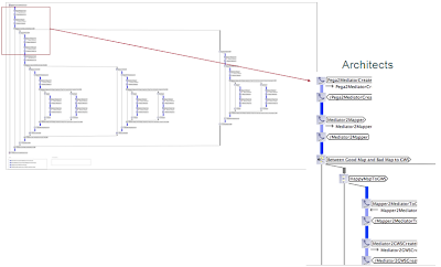
The Application of Testable Architecture

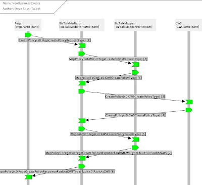
A dynamic model is based on formal methods, subsequently enabling designer to type check and simulate the proposed model against the refined requirements and the quality model. This part of the modelling discipline is inductive and primarily it allows design and requirement defects to be found and fixed prior to coding. Testable Architecture (TA) is the core engine of the innovation process model and key to the success of the proposed idea, i.e. the Mobile Broker Quest. TA is a methodology that abstracts the complexity of formal methods, pi calculus [Miln80a] [Miln80b] [Miln93], Petri nets [Pet62] and Z Notation to provide a “run time simulation engine” and type check compiler to dynamic models. It fundamentally has the capability of blending structural modelling with inductive modelling, acting as a compiler to design and models. As we journey through the process of building a dynamic representation of the requirement that describe the phenomenon of two participants booking appointments, we are able to exercise the dynamic model to verify and validate against two key question: 1) Is the model representing the right thing?; and 2) Is the model representing the thing right?
In Figure 6, we illustrated the Coloured Petri Net Model of the to-be process highlighting the dynamics of the waiting line for Brokers. We exploited the simulation engine of CPN to assess the model against the quality attributes (see Figure 2) and constraints, to validate if the proposed model conforms to the business values and goals.Coloured Petri Net [Jeff91] is a modelling technique to model parallel behaviour and high-level programming languages to define data, functions, and computation on data. The process model is represented by token exchange between different parts of the Petri Net wherein places are connected to transitions via arcs. Tokens are inserted or removed from places, which carry, as a timestamp, the deterministic or randomly distributed temporal length of the transition they enable.


Figure 5 The Meta Model of the Mechanics of CPN

Formal and Dynamic Modelling

In Figure 6, we illustrate a Petri Net model of a waiting line component of the Broker appointment systems. We employ Petri Net to model the queue wherein simulation processes are performed to understand how the queues work under different condition, e.g. an increase in appointment request and continuously check against conformance. In order to emulate the dynamics of the waiting we use some of the historical data of the existing broker quest system and couple the statistics with some probabilistic model. Based on the empirical research of the queuing theory, we assigned the following distribution behind the CPN model for simulation 1) the arrival rate follows a Poisson distribution, 2) the buffering rate of the queue follows a normal distribution and the processing time of servers follows an Exponential distribution and the waiting line follows a FIFO structure.

Figure 6 CPN Model of the Waiting Line

Observations

Consider Figure 7, where given a burst of 1 appointment request per 10 minutes to 1 appointment request per 3 minutes, the graph shows the gap between the input rate against the output rate. It justifies that the close proximity between the input and output rate shows that the service rate of the Queue System is adequately lower than the input rate. The two graphs differentiate the latency added to the queue system.


Figure 7 Waiting Line Dynamics of Mobile Broker Quest

In Figure 8, the graph reports on the time taken for a large sample of appointment requests to leave the system. The objective is to estimate the number of brokers waiting for more than n minutes (where n is defined by the SLA) that exist given an input burst. The graph shows the period of time a number of brokers take to meet an underwriter, e.g. over hundred appointment requests, a broker take 12 minutes. Hence using such analysis, a threshold can be established to identify those brokers that have a probability of waiting for too long.

Figure 8 Waiting Time of Broker

In order to reduce the number of variables in the experiments, we employed the Taguchi Method of Design of Experiment (DoE), used to determine the relationship between the different factors (Xs) affecting a process and the output of that process (Y). In the defined quality model we are seeking the fundamental SLAs of the MBQ which is to increase the number of appointments in a day to increase revenue in new business. So the function exercised into DoE is as follows:


DoE establishes the most important Xs, of the function to reduce the number of simulations against the SLAs.The iterative process of simulating the dynamic model (see Figure 9) leads to the reinforcement and refinement of the requirements and containment of design defects [Boeh76]. The refined requirements are validated and transformed into formal specifications that are given to the designer of the solution architect.The iterative process of simulating the dynamic model (see Figure 9) leads to the reinforcement and refinement of the requirements and containment of design defects [Boeh76]. The refined requirements are validated and transformed into formal specifications that are given to the designer of the solution architect.

Figure 9 Iterative Refinement of Requirement


The Solution Architecture

The architecture lays the foundation for analytical optimization of function, cost, quality and performance by gaining understanding of: 1) how the system and the system elements function ideally; 2) understanding of the interfaces and their interactions and 3) the understanding of behaviours influenced by the interactions as formalized by Testable Architecture. The process of modelling the latter can only be formally understood by exercising Testable Architecture.

As the solution architecture is formulated, the continuity of the innovation life cycle follows the path of the classical Software Development Life Cycle for coding and testing which ideally fits into the constraints of the Spiral Model.

Conclusion

MBQ yields to an improved time management strategy, increasing the number of brokers an underwriter can meet. It fundamentally addresses the problem of customer intimacy and customer satisfaction as broker may plan their day in advance. The capability of MBQ enables the insurer to maximise the probability of winning of potential business by reducing the number of broker walkouts. In the journey towards the MBQ, we have demonstrated the application of TRIZ to successfully provide the principles required to enhance the process of seed idea generation. Those principles force us to think laterally which ensures that key attributes of a solution are not missed as they are very often during solution envisioning exercise. We also observed that Innovation endeavours carry several facets of the unknowns and variations that require inductive models to test their viability at the early stages of requirements. Hence, we proposed a blended modelling approach, founded on the discipline of Testable Architecture to apply simulation and validation to the proposed model of the broker appointment system.

Reference


[Boeh76] Boehm B W, “Software Engineering”, IEEE Trans. Computers, pp. 1,226 - 1,241, December 1976

[Gar93] Garlan D, Shaw M, “An Introduction to Software Architecture, in Advances in Software Engineering and Knowledge Engineering” Vol 1, ed. Ambriola and Tortora World scientific Publishing Co., 1993

[Jeff91] Jeffrey J M, “Using Petri nets to introduce operating system concepts”, Paper presented at the SIGCSE Technical Symposium on Computer Science Education, San Antonio, USA, 7-8 March 1991

[Kap96] Kaplan S, “An Introduction to TRIZ – The Russian Theory of Invention Problem Solving”, Ideation Intl Inc, 1996

[Miln80a] Milner R, “A Calculus of Communicating Systems”, Lecture Notes in Computer Science, volume 92, Springer-Verlag, 1980

[Miln80b] Milner R, “A Calculus of Communicating Systems”, Lecture Notes in Computer Science, volume 92, Springer-Verlag, 1980

[Miln93] Milner R, “The Polyadic pi-Calculus: A Tutorial”, L. Hamer, W. Brauer and H. Schwichtenberg, editors, Logic and Algebra of Specification, Springer-Verlag, 1993

[Oud02] Oudrhiri R, “Une approche de l’évolution des systèmes,- application aux systèmes d’information”, ed.Vuibert, 2002

[Pet62] Petri C A, "Kommunikation mit Automaten", PhD thesis, Institut f¨ur instrumentelle Mathematik, Bonn, 1962

[Shaw01] Shaw M, “The coming-of-age of software architecture research”, in Proceedings of ICSE, pp. 656–664, Carnegie Mellon University, 2001

[Tal04] Ross–Talbot S, “Web Service Choreography and Process Algebra”, W3C Consortium, 2004

[Tal09] Ross-Talbot S, “
Savara - from Art to Engineering: It’s all in the description”, University of Leicester, Computer Science Seminar, 2009

[Yang06] Yang H et al, “Type Checking Choreography Description Language”, Lecture Notes in Computer Science Springer-Berlin / Heidelberg, Peking University, 2006

[Yoji90] Akao Y, “Quality Function Deployment: Integrating Customer Requirements into Product Design” (Translated by Glenn H. Mazur), Productivity Press, 1990

Saturday 26 September 2009

Testable Architecture: The Device to Craft Complex Communicating Systems

Introduction
It is very often argued that Software Engineering within distributed system is an engineering of complex system. According to Gödel incompleteness theorem, a complex system can be defined as one that can only be modelled by an infinite number of modelling tools (Chai71). The development of distributed systems in domains like telecommunications, industrial control, supply-chain and business process management represents one of the most complex construction tasks undertaken by software engineers (Jenn01) and the complexity is not accidental but it is an innate property of large systems (Sim96).

In distributed systems we observe emergent behaviour since logical operations may require communicating and multi channel interactions with numerous nodes and sending hundreds of messages in parallel. Distributed behaviour is also more varied, because the placement and order of events can differ from one operation to the next. Modelling the interactions of distributed system is not straight forward and inherently demands a multi-disciplinary approach and a change in traditional mindset to be resolved.
A Multi-disciplinary Class of Problems
The class of problems of modelling distributed systems is multidisciplinary, suggesting that there are several ways of modelling the problems attributes and we were required to combine several of these approaches and models, as Figure 1 shows:
Figure 1 Multi-disciplinarism in Modelling

Arguably, there are two types of modelling approaches, inductive and deductive, within the field of software engineering.
  • Deductive Modelling includes the aspect of structural, functional and collaborative designs and is commonly used in classical software engineering, such as Class Diagrams, Sequence Diagrams, Object Diagrams, Entity Relationship Diagrams (ERD), Data Flow Diagrams (DFD), Flow Charts, Use Cases, etc…
  • Inductive Modelling, are critical dynamic modelling techniques that primarily characterise the aspect of non-determinism within a system mainly arising from the occurrence of emergent behaviour and interactions. Commonly used techniques are formal methods (e.g. Testable Architecture), simulations and probabilistic models of the software artefact.

Modelling Concepts and Techniques
Unlike many engineering fields, software engineering is a particular discipline where the work is mostly done on models and rarely on real tangible objects (Oud02). According to Shaw, (Shaw90), Software engineering is not yet a true engineering discipline but it has the potential to become one. However, the fact that software engineers’ work mainly with models and a certain limited perception of reality, Shaw believes that the success in software engineering lies in the solid interaction between science and engineering.

In 1976, Barry Boehm (Boeh76) proposed the definition of the term Software Engineering as the practical application of scientific knowledge in the design and construction of computer programs and the associated documentation required to develop, operate, and maintain them. This definition is consistent with traditional definitions of engineering, although Boehm noted the shortage of scientific knowledge to apply.

On one hand, science brings the discipline and practice of experiments, i.e. the ability to observe a phenomenon in the real world, build a model of the phenomenon, exercise (simulate or prototype) the model and induce facts about the phenomenon by checking if the model behaves in a similar way to the phenomenon. In this situation, the specifications of the phenomenon might not be known upfront but induced after the knowledge about the phenomenon is gathered from the model. These specifications or requirement are known a posteriori.

On the other hand, engineering is steered towards observing a phenomenon in reality, deducing facts about the phenomenon, build concrete blocks; structures (moulds) or clones based on the deduced facts and reuse these moulds to build a system that mimics the phenomenon in reality. In this situation, the specifications of the phenomenon are known upfront, i.e. deduced before even constructing any models, whilst observing the phenomenon. The process of specifying facts about the phenomenon is rarely a learning process, and requirements are known a priori.

The scientific approach is based on inductive modelling and the engineering approach is based on deductive modelling. Usually in software engineering we are very familiar with the deductive modelling approach, exploiting modelling paradigm such as UML, ERD, and DFD that are well established in the field. However, the uses of inductive modelling techniques are less familiar in business critical software engineering, but applied extensively in safety critical software engineering and academia. Typically, inductive modelling techniques are experiments carried out on prototypes, or simulation of dynamic models which are based on mathematical (formal methods), statistical and probabilistic models. The quality of the final product lies in the modelling power and the techniques used to express the problem. As mentioned earlier, we believe that the power of the modelling lies in the blending of the inductive and deductive modelling techniques.

The rationale of integrating inductive modelling techniques within the domain of our study is due to the elements of non-determinism, emergent behaviours, communicational dynamics which are those parts of the problem that cannot be known or abstracted upfront i.e. a priori. These elements differs from those parts of the problem that can be abstracted from a priori based on experience and domain knowledge, which are normally deduced and translated into structures or models (moulds) i.e. using deductive modelling techniques.

Inductive modelling techniques require a different approach of addressing the problem attributes. In these circumstances, we tend to believe that the requirements are false upfront, and the objective is to validate these requirements against predefined quality attributes. To do so, we build formal models (formal methods) to mimic the functionalities of the suggested requirements and run the models (dynamically) to check if the models conform to the expected output and agreed quality. The modelling tools are dynamic in nature, and very often they offer themselves very easily to simulation engines and formal tests that allow system designers to run and exercise the designs, to perform model validation and verification. Through several simulation runs, the models are modified, adjusted and reinforce until they match, to certain level of confidence, the quality attributes.

Testable Architecture as a Blended Modelling Approach
For many years, computer scientists have tried to unify both types modelling techniques in order to capture the several facets of the distributed communication systems and demonstrate the power of modelling to develop software artefacts of high quality.

The development of distributed messaging system is a complex activity with a large number of quality factors involved in defining success. Despite the fact that inductive modelling is scientifically thorough for analysing and building quality engineered systems, it brings additional cost into the development life cycle. Hence, a development process should be able to blend inductive and deductive modelling techniques, to adjust the equilibrium between cost (time resource) and quality. As a result, the field of software process simulation has received substantial attention over the last twenty years. The aims have been to better understand the software development process and to mitigate the problems that continue to occur in the software industry which require a process modelling framework.
When it comes to modelling the interaction and communication of Distributed System, Choreography Description Language (CDL) is one of the most efficient and robust tool. CDL forms part of Testable Architecture, hereafter TA, and is based on pi calculus (Miln99), which is a formal language to define the act communicating.
Many other formal methods exist such as B Methods, Z Notations and lambda calculus that are used to unambiguously describe software requirements. However when it comes to describing distributed interactions of several participants, they fail, since they were not design to do so. Lambda calculus was designed for parametric description of passing arguments across functions; Z Notation was designed to classify and group attributes of the problem domain into logical sets; and B Methods was designed to describe requirement into logical and consistent machines. Pi calculus is a formal language that uses to concept of channels and naming to describe interactions and fits very well in the problem domain of distributed systems.
Unlike other modelling frameworks, TA is not limited to deductive and static modelling techniques, as it uses pi calculus based on non-deterministic models, that are well known within the academic world, but not yet of a common use within industry. In fact TA acts as a natural “glue” to blend the various modelling approaches providing a framework with the primary objective of removing the characteristic of ad-hocness and ambiguity within the modelling Process.
Using TA, the formal description of the requirements can be translated into different types of modelling tools starting with dynamic modelling tools (inductive modelling) such as Coloured Petri Nets (CPN) and prototyping, then moving to event based modelling tools such as State Chart Diagrams and Sequence diagrams and finishing with structural modelling tools (deductive modelling) such as class diagrams. Throughout the translation process, the specifications and requirements can be tested, validated and reinforce.

Case Study: Testable Architecture used in Large Communication Model of Business Critical Systems
In the case study, we focus on the fundamental problem of underwriting within a global insurance group, which includes the characteristics of Underwriting Workflow System, Policy Manager, Document Management System and the Integration Layer.

We demonstrate how TA is used to reinforce the power of modelling by avoiding classical modelling pitfalls, defining traceability across the lifecycle, providing a reference model through iterations, and addressing defects at early stage, hence increasing the maturity of the process model.

As we mentioned earlier, the design approach employs both the deductive and inductive modelling techniques, and TA employs a formal method, Pi Calculus, that provides the ability to test a given architecture, which is an unambiguous formal description of a set of components and their ordered interactions coupled with constraints on their implementation and behaviour. Such a description may be reasoned over to ensure consistency and correctness against requirements.

The Communication Architecture
The architecture provides communication management and enablement of external systems deployed over an ESB layer, conforming to the principle and discipline of SOA. The architecture diagram, Figure 2, outlines the communication between an Underwriting Workflow System and a Policy Manager (PM) . The communication is handled by the integration layer, employing BizTalk as technology and the Underwriting Workflow System is implemented using Pega PRPC.

The primary use of TA in the given problem domain, is to achieve a model of communication that can evolve to allow BizTalk to move from being purely an EAI to the capability of an ESB wherein heterogeneous types of communication which includes communication will be possible. Such conversation will be with Document Management Systems, Claims Repository Service, external Rating Services and others. In our problem domain, BizTalk maps the message of Pega PRPC, hereafter Pega, to the legacy Policy Manager. This is carried by transforming the data structure of the Pega messages into the data structure of native Policy Manager. There are 3 generic types of communication that describes the conversation between Pega and BizTalk.


Figure 2 Communication Model

The communication model illustrates 3 communication types 1) notification, error and data, expressed as CS_Not, CS_Err and CS_Dat respectively which is channelled from Pega to BizTalk. BizTalk accesses the data mapping schema and transform the incoming schema into response schema which is agreed by the Policy Manager. The Data Mapper is logically represented by the ERD.

From BizTalk to the Policy Manager, there are two types of communication which are 1) notification, CS_Not and 2) Data, CS_Dat. The communication model represented follows an asynchronous mode, which is handled by the Request/Reply map repository. The latter holds the state that assigns the corresponding response from the Policy Manager to a Request from Pega. There is a polling mechanism to notify Pega that a response has been received for a corresponding request.
There are 3 return communication types from the Policy Manager to BizTalk which are CS_Not, CS_Err and CS_Dat. The latter holds the data which is required by Pega to update any underwriting transactions. As we modelled the communication using TA, it has been observed that the existing legacy Policy Manager interface does not differentiate between success and failure response, hence there is no separation of identity between the error and success, which complicates the design of the integration layer. The design flaw has been identified whilst validating and type checking the communication model with TA. This has lead to some mistake proof mechanism within BizTalk to manage error and trace the error back to the presentation layer, i.e. General Underwriting System. BizTalk has to transform the Policy Manager schema into a structure agreeable by Pega. The communication medium employed across Pega, BizTalk and Policy Manager is SOAP.
The process starts at the requirement gathering phase, where TA is used to identify the core aspects of the communication which are in our context, the Pega component, The BizTalk component and Policy Manager (PM), as shown in Figure 3.


Figure 3 Requirement communication model

At the very early stage of design, while validating the communication with TA through formal checking, it has been observed that the BizTalk component includes two primary modules, which is required to be modelled separately, and these are the Mapper component and the Mediator component respectively. This is a typical problem of separation of concerns. The separation showed that the mediator service is solely concerned with the orchestration of the communication model whereas the mapper service is related to the data modelling which ought to be abstracted to the problematic of Canonical Data Model within an ESB. Using classical modelling techniques, purely static design such as sequence diagram, this dichotomy would have been missed in requirement and only be found at the late stage of design or coding. It is also possible that the separation would have been missed completely, adding overheads and reworks to preserve the characteristic of extensibility to the architecture.


Figure 4 Conversation Model

Whilst requirements are gathered, a model of the conversation within problem emerges as shown in Figure 4. This is static diagram that simply lays out the roles, the swim lanes (see Figure 3), and who can talk to who. This enables us to manage the conversation in the system and to also extend the model to add new components and test if the communication model still holds when new participants are added.
The next step is to bind the model in Figure 3 to a choreography, which will enable us to type check the model against the requirement in order to validate the model and remove ambiguity in the requirements for the communication model. The choreography is shown in Figure 5.
Figure 5 Architecting the Design

The binding process involves the process of referencing the model in the requirement and binding the interactions. The binding process also has the effect of filling in some of the missing information on identity and business transactions.

With a bound model, the choreography in Figure 5 can be exercised in order to prove the model against the architectural parameters as shown in Figure 6. The model shows the participants which are Pega, conversing with the BizTalk mediator, then the mapper (for data transformation) to finally be passed to the Policy Manager participant.

Figure 6 Proving the Communication Model

During the test of the architecture, the proof goes green (see Figure 6) if the configuration and parameters or more precisely the types of the interactions are correct and should it be red, the proof reveals that the model deviates from the requirements, highlighting the defects.

Thus for each interaction we can see clearly what the identity is, what we call the type for that identity (the token or tokens) and the Xpath expressions which when executed over the example message (in our case the risk xml of Pega and the Policy Manager Process UW xml) return the appropriate values.

Blended Modelling Approach

After the proof of the model is demonstrated, we believe that the models are true and they conform to the pre defined requirements and many of the ambiguities in the requirements have been detected and consequently resolved at the requirement and design phase of the Software Development Life Cycle (SDLC). Then, in exploiting the capabilities of model generation, TA provides us with a rich a proven set of artefacts such as UML designs and state-charts diagram of the model. In Figure 7, we show the state-charts generated from the proven dynamic models. This is typically the translation of the inductive models (the CDL model) to the more common deductive models (UML and BPMN). Then the course of the SDLC resumes with the normal route of the classical software engineering processes.

Figure 7 Generated UML Artefacts State Chart of the Underwriting System

The generated models along with auto-generated documentations are compiled into the design directives and coding principles that can be handed over to the software designer and the developers. The communication to these parties is founded on formal and mathematical checks which makes the design and the development of the system far less error prone.

Conclusion
In employing TA, we were able to identify business and core service easily and test them against requirements for the mediator business service and mapper core service. We worked very closely with key decision makers to ensure a full understanding and gain agreement on requirements through inductive modelling of requirements and the collaboration model that is embodied in TA. This allowed rapid turn-around with Business Analyst and reduced the overall design time.

Secondly we were able to detect errors both as conflicting requirements (reported back and then remediated with the stakeholders) and technical design errors prior to coding, the latter being the legacy Policy Manager’s error handling problem. We were also able to simplify the design segmenting it and ensuring that it truly represented the requirements through TA.

Finally, TA enabled the generation of implementation artefacts, such as UML designs and state charts that were guaranteed to meet requirements and were an order of magnitude more precise which reduced the communication need to ensure a high quality delivery. This is typically the capability of TA to blend the inductive with the deductive modelling techniques.

Reference


(Chai71) Chaitin G J, “Computational Complexity and Godel's Incompleteness Theorem”, ACM SIGACT News, No. 9, IBM World Trade, Buenos Aires, pp. 11- 12, April 1971


(Jenn01) Jennings N R, “An Agent-based approach for building complex software systems”, Communications of the ACM, Vol 44, No. 4, April 2001


(Sim96) Simon H A, “The Sciences of the Artificial”, MIT Press, 1996


(Oud02) Oudrhiri R, “Une approche de l’évolution des systèmes,- application aux systèmes d’information”, ed.Vuibert, 2002


(Shaw90) Shaw M, “Prospects for an Engineering Discipline of Software”, IEEE Journal, Carnegie Mellon University, 1990


(Boeh76) Boehm B W, “Software Engineering”, IEEE Trans. Computers, pp. 1,226 - 1,241, December 1976


(Miln99) Milner R, “Communicating and Mobile Systems”, Cambridge Press, June 1999


Tuesday 28 July 2009

Evolution of Systems

In the discussion on evolution of systems, Hugues Bersini (Bersini05) states that:

Of the many types of systems organisations models, those that are in the form of networks and which are based on distributed architectures are the ones that survive and are economically most viable.

The study on dynamic evolution (Fung04) supports Bersini’s statement as the authors explain that one can easily achieve evolution in a component-based distributed system. In this paper, Hay Fung explains the abstraction of components and their connectors facilitates system structures to accommodate changes, and the process of accommodation becomes an innate property of the system.

Currently the software industry is in favour of the iterative and incremental development approach over the traditional waterfall model, in order to achieve flexible processes that handle requirements and reduce the risk by deploying smaller changes. In such an environment, dynamic evolution provides the flexibility in implementing changes to unforeseen and fluctuating business requirements which is very true for the type of economic climate we are now living in. We have moved form the industrial age to the knowledge age.

Evolution is a key factor to software systems, because these types of systems are never isolated, but implicitly constrained by their users, the communication with external systems (man or machines) and the infrastructures (software or hardware) with which they communicate (Oud02). Each adjustment or modification from any connecting peers (interactive participants) may change or affect the internal system, hence the state machine. The system may be provided with some resiliency and intelligence through predefined logic, to either protect itself from these changes or adapt itself to these changes, depending on the hostility of the environment. In other words some decision dominance may be given to the system, defining an aspect of autonomy, and since the working environment is non-deterministic, the system will need to adapt and re-adapt itself, changing its course many times during its life time (Oud02)

Unfortunately, investments in software systems are mostly focus on designing systems based on strict protocols and precise specifications and constraints, thus restricting the systems from its external communication. If we agree that software systems are never isolated, these types of design approach (strict protocols and precise specifications) go against the natural progress of software systems. The need for evolution in the design of complex enterprise system can be mapped to Lehman’s 8 laws of software evolution (Leh80).

We considered Lehman’s 8 laws of evolution to establishing a new discipline to the formulation of a framework which will attempt to incorporate some aspects of evolution within enterprise wide systems.

Law (3) Self Regulation - Global system evolution processes needs to be self-regulating to adapt to change. In mathematical terms, these regulations are pre-defined elements of a subset which are in turn elements of a global set, i.e. the enterprise architecture.

Law (4) Conservation of Organisational Stability - Unless feedback mechanisms are appropriately adjusted, recorded and statistically analysed, average effective global productivity rate in an evolving system tends to remain constant over product or service lifetime.

Law (5) Conservation of Familiarity – In general, the incremental growth and long term growth of systems tend to decline. Over the lifetime of a system, the incremental system change in each release is approximately constant.

The laws 3,4,5 of software evolution, has not been the main point of focus, in this blog article, since they have some dependencies on other laws and are more abstract in nature. For instance laws 3 and 4, self-regulation and conservation of organizational stability respectively, are dependent on robust feedback mechanism which is law 8. Law 5, conservation of familiarity is very dependent on law 6 and 7 which are continuous growth and decline in quality. As a result, the following laws have been addressed in the research.

Law (1) Continuing Change – “A program that is used in a real-world environment must change, or become progressively less useful”. A software system is never isolated and constantly communicates with external entities, which during the course of conversation changes the state of the software continuously. These changes cause variations within the internal system and are required to be managed and monitored to ensure that the changes tallies with the changes of the organisation. Continuous change is the basic law of evolution and is inherently implied even if most of the time, the client does not explicitly state it.

Law (2) Increasing Complexity - “As a program evolves, it becomes more complex, and extra resources are needed to preserve and simplify its structure”. As the number of communication agents (Service Components and network elements) increases, the communication model tend to become more complex and non-deterministic. Within an enterprise wide architecture, the law also applies to the message, as the content of the message tend to become more complex as the organisation matures from a B2C business model to B2B business models, extra resources are needed to preserve or simplify the structure of the systems in terms of manageability and serviceability. In an attempt to address the problematic of complexity, many decision makers are tempted to move towards a more manageable character of a common data model, the substratum of their service bus, yet on the longer term, this solution proves gruelling to scale and adapt to external systems. The very symmetric nature of the data model tends to hinder the evolution of systems.

Law (6) Continuing Growth - “The functional capability of systems must be continually increased to maintain user satisfaction over the system lifetime”. Scalability of the functionalities is key in the design of extendable software solutions. Although software solutions may be well structured internally, exploiting the capabilities of hierarchically structured class libraries, the programs have grown large and monolithic, with a high degree of interdependence of the internal modules. The size of the programs and their relatively high level of user oriented interfaces make them inflexible and discomfited to use for the construction of new functions and applications or new service interactions. As a result, new applications usually have to be constructed at a relatively low level, as compiled programs, which are expensive and inflexible. The high degree of integration at the class library level makes it difficult to construct heterogeneous applications that use modules from different systems, since there is a lack of abstraction. This problem can be addressed by distributed systems which allow software modules to be represented as either stand alone or pluggable components in a distributed application through defined interface or configurable resource adapters. This technique will require the compositions of meta models and the continuous process of abstracting (reinforcing the meta models from lesson learned) and concretizing (deriving pluggable components from the meta model to satisfy the custom requirements of specific scenarios), hence scaling the capabilities of the systems.

Law (7) Decline Quality – “Unless rigorously adapted to take into account for changes in the operational environment, the quality of a system will appear to be declining.” In order to manage the quality of the system, a quality process has to be put in place to improve both the operational environment and the system itself. In many studies directed to the evolution of computerised system (Zhan01, Mikk00 and Kout01), the aspect of quality management is very rarely considered. Yet, Lehman stresses that a decline in quality influences the viability of an adaptive system and for diverse reasons this is often the case for system that evolves. We firmly believe that the aspect of quality modelling and quality awareness has to be embedded within the system gene (at the code level if necessary). We refer to this model as the Run Time Quality Assurance (RTQA), modelled in the shape of an algorithm called the BipRyt algorithm (Mak04). The BipRyt algorithm was designed primarily to take into account the operational environment and steer the system, adjust its parameters to conform to the environment at run time, thus preserving the quality of the system as the system scales. The algorithm provides the aspect of autonomy to the collaborative participants of a system, which exploits a multi-purpose decision making mechanism for the management, control and optimisation of computational resources (e.g. node, CPU, channel, etc). The decision matrices regard all these participants as resources with diverse economical values (values which may be relative to each user).

Fundamentally the algorithm is founded on the basis that:

Rather than just using Quality modelling tools (such as the House of Quality, Analytical Hierarchy Process and Hypothesis Testing) as requirement and design activities, the BipRyt mechanism has embedded these approaches as a feature of the system (automating the methods of the tools) and made the system self-aware of its own quality attributes and react accordingly when there are SLA breaches or increased demand of resources

Law (8) Feedback System – “Evolution processes are multi-level, multi-loop, multi-agent feedback systems.” Feedback is a strong management tool to revise and improve a system. Since, software systems are never isolated, a robust feedback mechanism is required to validate the compliance of system functions over which the system developers have little or no control (Morr00). Due to the lack of control over the external components, the most economic approach is to implement feedback mechanism to obtaining statistics on how the components and the interface behaves, and then evolve in the light of that feedback. We have formulated and implemented an automated feedback mechanism (based on the concept of hypothesis Testing and Design of Experiment) within the decision process of resource management of service components of enterprise wide architectures to create an adaptive, decision making algorithm.

However, in order to design systems that evolve, one is also required to consider the aspect of autonomy within the distributed participants of the system. The study on the drive behind evolution of software architecture (Estu99) shows that systems are evolving under the pressure of a number of factors, which are: 1) distribution requires components to be more autonomous and to communicate through explicit means (not linked); 2) maintainability does not requires changing of the source code of components; 3) evolution of system and mobility require keeping components independent and autonomous and 4) Cost requires buying instead of building.

We believe that there is a 9th law missing in Lehman’s law of software evolution which is:

“For a system to evolve, it has to be distributed in nature with autonomous parts collaborating and exercising the 8 laws.”

What is a neurone on its own... what is an ant on its own? In my next blog, I will be discussing about autonomous Systems.

References:

(Bersini05) Bersini H, “Des réseaux et des sciences – Biologie, informatique, sociologie: l’omniprésence des reséaux”, Vuibert, Paris 2005

(Fung04) Hay Fung K, Low G, Bay P K, “Embracing dynamic evolution in distributed systems Software”, IEEE Vol. 21, Issue 2, pp. 49 – 55, March-April, 2004

(Oud02) Oudrhiri R, “Une approche de l’évolution des systèmes,- application aux systèmes d’information”, ed.Vuibert, 2002

(Leh80a) Lehman MM, “On Understanding Laws, Evolution and Conservation in the Large Program Life Cycle”, Journal of System and Software, vol 1, no. 3, 1980

(Zhan01) Zhang T, “Agent-based Interperability in Telecommunications Applications”, PhD Thesis, University of Berlin, 2001

(Mikk00) Mikkonen T; Lahde E; Niemi J; Siiskonen M, “Managing software evolution with the service concept”, in the Proceedings of International Symposium on Principles of Software Evolution, pp 46 – 50, 2000

(Kou01) Koutsoukos G, Gouveia J, Andrade L, Fiadeiro J L, “Managing Evolution in Telecommunications Systems”, IFIP Conference Proceedings, Vol. 198, 2001

(Mak04) Makoond B, Khaddaj S, Saltmarsh C, "Conversational Dynamics", Kingston University, February 2004

(Morr00) Morrison R, Balasubramaniam D, Greenwood R M, Kirby G N C, Mayes K, Munro D S, Warboys B C, “A Compliant Persistent Architecture, in Software Practice and Experience” vol. 30, no. 4, pp. 363 – 386, 2000

(Estu99) Estublier J, “Is a process formalism an Architecture Description Language?”, Dassault Système / LSR, International Process Technology Workshop (IPTW), Villard de Lans, France, September, 1999