It is very often argued that Software Engineering within distributed system is an engineering of complex system. According to Gödel incompleteness theorem, a complex system can be defined as one that can only be modelled by an infinite number of modelling tools (Chai71). The development of distributed systems in domains like telecommunications, industrial control, supply-chain and business process management represents one of the most complex construction tasks undertaken by software engineers (Jenn01) and the complexity is not accidental but it is an innate property of large systems (Sim96).
The class of problems of modelling distributed systems is multidisciplinary, suggesting that there are several ways of modelling the problems attributes and we were required to combine several of these approaches and models, as Figure 1 shows:

- Deductive Modelling includes the aspect of structural, functional and collaborative designs and is commonly used in classical software engineering, such as Class Diagrams, Sequence Diagrams, Object Diagrams, Entity Relationship Diagrams (ERD), Data Flow Diagrams (DFD), Flow Charts, Use Cases, etc…
- Inductive Modelling, are critical dynamic modelling techniques that primarily characterise the aspect of non-determinism within a system mainly arising from the occurrence of emergent behaviour and interactions. Commonly used techniques are formal methods (e.g. Testable Architecture), simulations and probabilistic models of the software artefact.
Modelling Concepts and Techniques
Unlike many engineering fields, software engineering is a particular discipline where the work is mostly done on models and rarely on real tangible objects (Oud02). According to Shaw, (Shaw90), Software engineering is not yet a true engineering discipline but it has the potential to become one. However, the fact that software engineers’ work mainly with models and a certain limited perception of reality, Shaw believes that the success in software engineering lies in the solid interaction between science and engineering.
In 1976, Barry Boehm (Boeh76) proposed the definition of the term Software Engineering as the practical application of scientific knowledge in the design and construction of computer programs and the associated documentation required to develop, operate, and maintain them. This definition is consistent with traditional definitions of engineering, although Boehm noted the shortage of scientific knowledge to apply.
On one hand, science brings the discipline and practice of experiments, i.e. the ability to observe a phenomenon in the real world, build a model of the phenomenon, exercise (simulate or prototype) the model and induce facts about the phenomenon by checking if the model behaves in a similar way to the phenomenon. In this situation, the specifications of the phenomenon might not be known upfront but induced after the knowledge about the phenomenon is gathered from the model. These specifications or requirement are known a posteriori.
On the other hand, engineering is steered towards observing a phenomenon in reality, deducing facts about the phenomenon, build concrete blocks; structures (moulds) or clones based on the deduced facts and reuse these moulds to build a system that mimics the phenomenon in reality. In this situation, the specifications of the phenomenon are known upfront, i.e. deduced before even constructing any models, whilst observing the phenomenon. The process of specifying facts about the phenomenon is rarely a learning process, and requirements are known a priori.
The scientific approach is based on inductive modelling and the engineering approach is based on deductive modelling. Usually in software engineering we are very familiar with the deductive modelling approach, exploiting modelling paradigm such as UML, ERD, and DFD that are well established in the field. However, the uses of inductive modelling techniques are less familiar in business critical software engineering, but applied extensively in safety critical software engineering and academia. Typically, inductive modelling techniques are experiments carried out on prototypes, or simulation of dynamic models which are based on mathematical (formal methods), statistical and probabilistic models. The quality of the final product lies in the modelling power and the techniques used to express the problem. As mentioned earlier, we believe that the power of the modelling lies in the blending of the inductive and deductive modelling techniques.
The rationale of integrating inductive modelling techniques within the domain of our study is due to the elements of non-determinism, emergent behaviours, communicational dynamics which are those parts of the problem that cannot be known or abstracted upfront i.e. a priori. These elements differs from those parts of the problem that can be abstracted from a priori based on experience and domain knowledge, which are normally deduced and translated into structures or models (moulds) i.e. using deductive modelling techniques.
Inductive modelling techniques require a different approach of addressing the problem attributes. In these circumstances, we tend to believe that the requirements are false upfront, and the objective is to validate these requirements against predefined quality attributes. To do so, we build formal models (formal methods) to mimic the functionalities of the suggested requirements and run the models (dynamically) to check if the models conform to the expected output and agreed quality. The modelling tools are dynamic in nature, and very often they offer themselves very easily to simulation engines and formal tests that allow system designers to run and exercise the designs, to perform model validation and verification. Through several simulation runs, the models are modified, adjusted and reinforce until they match, to certain level of confidence, the quality attributes.
Testable Architecture as a Blended Modelling Approach
For many years, computer scientists have tried to unify both types modelling techniques in order to capture the several facets of the distributed communication systems and demonstrate the power of modelling to develop software artefacts of high quality.
Unlike other modelling frameworks, TA is not limited to deductive and static modelling techniques, as it uses pi calculus based on non-deterministic models, that are well known within the academic world, but not yet of a common use within industry. In fact TA acts as a natural “glue” to blend the various modelling approaches providing a framework with the primary objective of removing the characteristic of ad-hocness and ambiguity within the modelling Process.
Case Study: Testable Architecture used in Large Communication Model of Business Critical Systems
In the case study, we focus on the fundamental problem of underwriting within a global insurance group, which includes the characteristics of Underwriting Workflow System, Policy Manager, Document Management System and the Integration Layer.
We demonstrate how TA is used to reinforce the power of modelling by avoiding classical modelling pitfalls, defining traceability across the lifecycle, providing a reference model through iterations, and addressing defects at early stage, hence increasing the maturity of the process model.
As we mentioned earlier, the design approach employs both the deductive and inductive modelling techniques, and TA employs a formal method, Pi Calculus, that provides the ability to test a given architecture, which is an unambiguous formal description of a set of components and their ordered interactions coupled with constraints on their implementation and behaviour. Such a description may be reasoned over to ensure consistency and correctness against requirements.
The Communication Architecture
The architecture provides communication management and enablement of external systems deployed over an ESB layer, conforming to the principle and discipline of SOA. The architecture diagram, Figure 2, outlines the communication between an Underwriting Workflow System and a Policy Manager (PM) . The communication is handled by the integration layer, employing BizTalk as technology and the Underwriting Workflow System is implemented using Pega PRPC.
The primary use of TA in the given problem domain, is to achieve a model of communication that can evolve to allow BizTalk to move from being purely an EAI to the capability of an ESB wherein heterogeneous types of communication which includes communication will be possible. Such conversation will be with Document Management Systems, Claims Repository Service, external Rating Services and others. In our problem domain, BizTalk maps the message of Pega PRPC, hereafter Pega, to the legacy Policy Manager. This is carried by transforming the data structure of the Pega messages into the data structure of native Policy Manager. There are 3 generic types of communication that describes the conversation between Pega and BizTalk.

Figure 2 Communication Model
From BizTalk to the Policy Manager, there are two types of communication which are 1) notification, CS_Not and 2) Data, CS_Dat. The communication model represented follows an asynchronous mode, which is handled by the Request/Reply map repository. The latter holds the state that assigns the corresponding response from the Policy Manager to a Request from Pega. There is a polling mechanism to notify Pega that a response has been received for a corresponding request.
The process starts at the requirement gathering phase, where TA is used to identify the core aspects of the communication which are in our context, the Pega component, The BizTalk component and Policy Manager (PM), as shown in Figure 3.

Figure 3 Requirement communication model

The next step is to bind the model in Figure 3 to a choreography, which will enable us to type check the model against the requirement in order to validate the model and remove ambiguity in the requirements for the communication model. The choreography is shown in Figure 5.
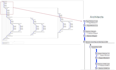
With a bound model, the choreography in Figure 5 can be exercised in order to prove the model against the architectural parameters as shown in Figure 6. The model shows the participants which are Pega, conversing with the BizTalk mediator, then the mapper (for data transformation) to finally be passed to the Policy Manager participant.
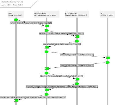
Figure 6 Proving the Communication Model
During the test of the architecture, the proof goes green (see Figure 6) if the configuration and parameters or more precisely the types of the interactions are correct and should it be red, the proof reveals that the model deviates from the requirements, highlighting the defects.
Thus for each interaction we can see clearly what the identity is, what we call the type for that identity (the token or tokens) and the Xpath expressions which when executed over the example message (in our case the risk xml of Pega and the Policy Manager Process UW xml) return the appropriate values.
Blended Modelling Approach
After the proof of the model is demonstrated, we believe that the models are true and they conform to the pre defined requirements and many of the ambiguities in the requirements have been detected and consequently resolved at the requirement and design phase of the Software Development Life Cycle (SDLC). Then, in exploiting the capabilities of model generation, TA provides us with a rich a proven set of artefacts such as UML designs and state-charts diagram of the model. In Figure 7, we show the state-charts generated from the proven dynamic models. This is typically the translation of the inductive models (the CDL model) to the more common deductive models (UML and BPMN). Then the course of the SDLC resumes with the normal route of the classical software engineering processes.

Figure 7 Generated UML Artefacts State Chart of the Underwriting System
The generated models along with auto-generated documentations are compiled into the design directives and coding principles that can be handed over to the software designer and the developers. The communication to these parties is founded on formal and mathematical checks which makes the design and the development of the system far less error prone.
Conclusion
In employing TA, we were able to identify business and core service easily and test them against requirements for the mediator business service and mapper core service. We worked very closely with key decision makers to ensure a full understanding and gain agreement on requirements through inductive modelling of requirements and the collaboration model that is embodied in TA. This allowed rapid turn-around with Business Analyst and reduced the overall design time.
Secondly we were able to detect errors both as conflicting requirements (reported back and then remediated with the stakeholders) and technical design errors prior to coding, the latter being the legacy Policy Manager’s error handling problem. We were also able to simplify the design segmenting it and ensuring that it truly represented the requirements through TA.
Finally, TA enabled the generation of implementation artefacts, such as UML designs and state charts that were guaranteed to meet requirements and were an order of magnitude more precise which reduced the communication need to ensure a high quality delivery. This is typically the capability of TA to blend the inductive with the deductive modelling techniques.
Reference
(Chai71) Chaitin G J, “Computational Complexity and Godel's Incompleteness Theorem”, ACM SIGACT News, No. 9, IBM World Trade, Buenos Aires, pp. 11- 12, April 1971
(Jenn01) Jennings N R, “An Agent-based approach for building complex software systems”, Communications of the ACM, Vol 44, No. 4, April 2001
(Sim96) Simon H A, “The Sciences of the Artificial”, MIT Press, 1996
(Oud02) Oudrhiri R, “Une approche de l’évolution des systèmes,- application aux systèmes d’information”, ed.Vuibert, 2002
(Shaw90) Shaw M, “Prospects for an Engineering Discipline of Software”, IEEE Journal, Carnegie Mellon University, 1990
(Boeh76) Boehm B W, “Software Engineering”, IEEE Trans. Computers, pp. 1,226 - 1,241, December 1976
(Miln99) Milner R, “Communicating and Mobile Systems”, Cambridge Press, June 1999
pretty impressive, and well written. When I talked to steve the last time he was fascinated by this :)
ReplyDeletecheers
Really great news!!! this information is well worth looking everyone. Good tips. I will be sharing this with all of my friends! Thank you for sharing valuable information. Go Car insurance comparison sites believes in respecting every customers privacy and helps customers to get hold the product which they are most in need of, taking care of their budget line. This site is quite confident and Continue reading.
ReplyDeleteThank you so much for taking the time for you personally to share such a nice info. I truly favor to reading your post
ReplyDelete________________________
Paint for mac
Thanks for sharing in detail. Your blog is an inspiration! Apart of really useful tips, it's just really ! This post will be effectively Just about everything looks good displayed.
ReplyDelete-----------------------
White card
They are becomes a more and more interesting from the starting lines until the end.jira software training
ReplyDeleteVery nice post here and thanks for it .I always like and such a super contents of these post.Excellent and very cool idea and great content of different kinds of the valuable information's.
ReplyDeletepython Training in chennai
python Course in chennai
Very Informative blog thank you for sharing. Keep sharing.
ReplyDeleteBest software training institute in Chennai. Make your career development the best by learning software courses.
azure certification in chennai
Xamarin Training Course in Chennai
Best Docker Training in Chennai
Those guidelines additionally worked to become a good way to
ReplyDeleterecognize that other people online have the identical fervor like mine
to grasp great deal more around this condition.
mysql online course in Chennai
unix certification in Chennai
IT training institute in Chennai
Thanks for sharing! Very helpful and well explained.
ReplyDeleteFull Stack Developer Course in Chennai
Great read! I learned something new today.
ReplyDeleteSalesforce Course in Chennai
Thanks for sharing! This was really helpful.
ReplyDeletesupply chain management course
Great read! I learned something new today.
ReplyDeleteTableau course in Chennai
Thanks for sharing! Very helpful and well explained.
ReplyDeleteServiceNow Course in Online
Thanks for sharing! Very helpful and well explained.
ReplyDeleteSalesforce Certification Online Course
Thanks for sharing! Very helpful and well explained.
ReplyDeleteCyber Security Online Training
Useful post, keep sharing more like this!
ReplyDeleteCCNA Course in Chennai
Great read! I learned something new today.
ReplyDeleteSalesforce Certification Online Course
Great read! I learned something new today.
ReplyDeleteSQL Course in Chennai
Thanks for sharing! This was really helpful.
ReplyDeleteData Analytics Online Certification Course
Thanks for sharing! This was really helpful.
ReplyDeleteTally Course in Chennai
Useful post, keep sharing more like this!
ReplyDeleteEthical Hacking Course in Chennai
Thanks for sharing! This was really helpful.
ReplyDeleteDigital Marketing Certification Course
Great read! I learned something new today.
ReplyDeletePower BI Certification Course
Great read! I learned something new today.
ReplyDeleteCyber Security Online Training
Thanks for sharing such a thoughtful and informative blog post. I truly appreciate the clarity and engaging style you used to explain the topic. It’s not often that I come across content that is both easy to follow and highly insightful. Looking forward to reading more of your work!
ReplyDeleteCloud Computing Online Course
Thanks for sharing! Very helpful and well explained.
ReplyDeleteData Analytics Online Course
Thanks for sharing! This was really helpful.
ReplyDeleteMicrosoft Azure Certification Course
Useful post, keep sharing more like this!
ReplyDeleteUI UX Design Online Course
Useful post, keep sharing more like this!
ReplyDeleteFull Stack Developer Online Training